
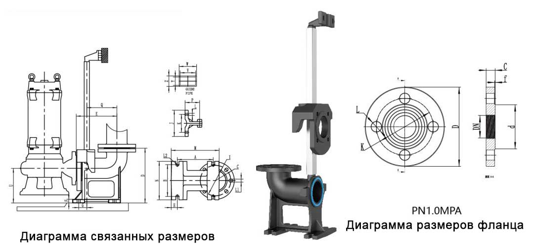
• Reinforcement to the pump with a flange complying with ISO 7005 - 92 standard.
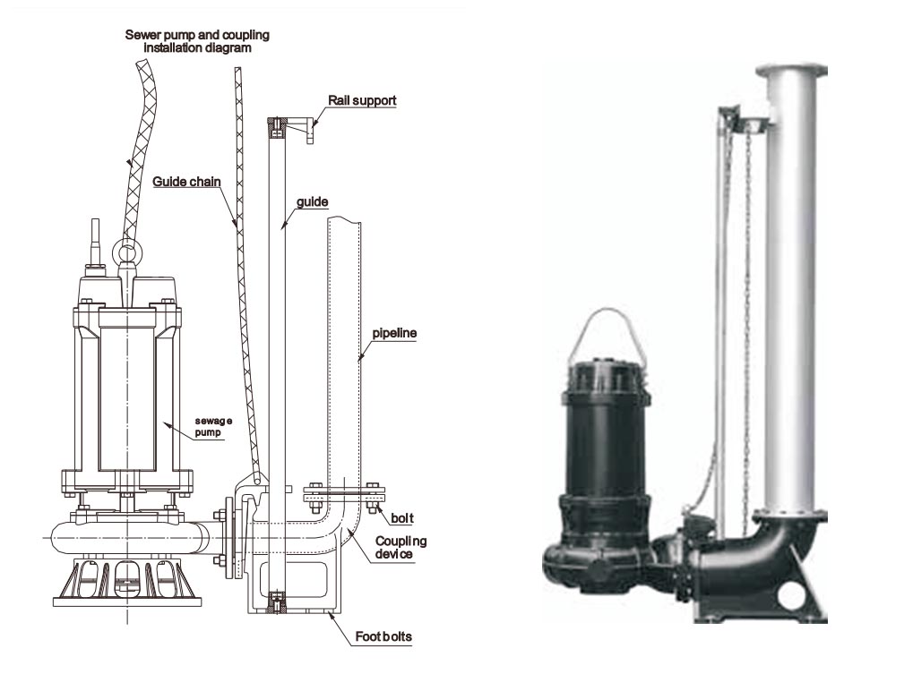
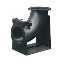
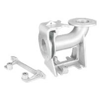
• The guide mounting system simply reduces and raises the pump to easily connect the pump to the pipeline, without entering the sump pit for easy maintenance and inspection.
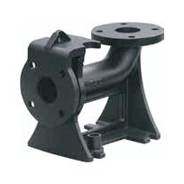
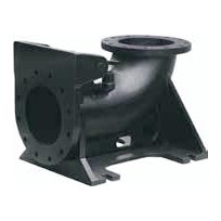
Ac Automatic Clutch
DN50 - 250 Light cast iron
DN50 - 600 Heavy cast iron
DN300 - 600 Light steel (welded)
DN50-200 (SS 304)
| Nominal diameter. | Hole spacing | Guide center distance | Hole | From stand to mounting surface | Door thickness | Long |
| (DN) | (M) | (Z) | (L3) | (W) | (X) | (Y) |
| 50 | 220 | 100 | 2-f12 | 70 | 20 | 265 |
| 65 | 240 | 130 | 2-f12 | 70 | 20 | 275 |
| 80 | 270 | 150 | 2-f12 | 80 | 20 | 315 |
| 100 | 305 | 170 | 2-f12 | 90 | 20 | 360 |
| 150 | 400 | 205 | 2-f16 | 80 | 15 | 465 |
| 200 | 485 | 280 | 2-f16 | 83 | 18 | 550 |
| 250 | 540 | 320 | 2-f16 | 95 | 20 | 610 |
| 300 | 560 | 340 | 2-f16 | 95 | 20 | 630 |
| 350 | 560 | 340 | 2-f16 | 95 | 20 | 630 |
| 400 | 610 | 370 | 2-f16 | 115 | 20 | 680 |
| 500 | 07 | 442 | 2-f24 | 120 | 25 | 777 |
| 600 | 805 | 540 | 2-f24 | 120 | 25 | 875 |
| 200 | 465 | 260 | 2-f16 | 83 | 18 | 530 |
| 250 | 525 | 305 | 2-f16 | 95 | 20 | 595 |
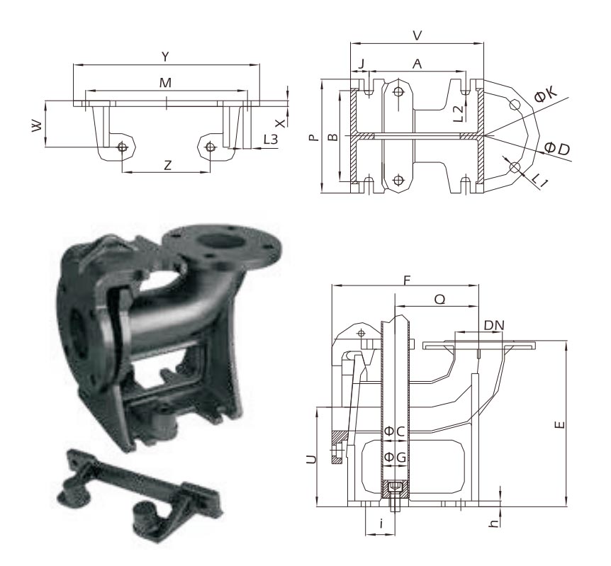
| Type | Nominal diameter. | Flange diameter. | Diameter of the central circle. | bolt hole | Fixed coupling bolt spacing | Catheter size internal diameter. O.D | Clutch height | Center length | Central height | Outlet pipeline | Base length | Base width | Front bracket to hole | Catheter hole into hole | Foundation thickness | base socket | Pressure Nomina | ||
| (DN) | (D) | (K) | (n-L1) | (A) | (B) | (φC) | (φG) | (F) | (E) | (u) | (Q) | (V) | (P) | (J) | (I) | (h) | (L2) | ||
| Heavy (cast iron) | 50 | 140 | 110 | 4-f14 | 166 | 138 | 26.5 | 32 | 210 | 230 | 130 | 155 | 210 | 160 | 22 | 25 | 12 | f16 | PN6 |
| 65 | 160 | 130 | 4-f14 | 185 | 170 | 26.5 | 32 | 245 | 260 | 150 | 175 | 235 | 200 | 25 | 40 | 12 | f16 | PN6 | |
| 80 | 190 | 150 | 4-f18 | 210 | 190 | 42 | 47 | 280 | 300 | 170 | 192 | 270 | 230 | 30 | 50 | 12 | f16 | PN6 | |
| 100 | 210 | 170 | 4-f18 | 256 | 225 | 42 | 47 | 340 | 355 | 200 | 233 | 320 | 270 | 32 | 60 | 15 | f20 | PN6 | |
| 150 | 265 | 225 | 8-f18 | 370 | 260 | 42 | 47 | 350 | 415 | 180 | 255 | 486 | 300 | 60 | 56 | 18 | f20 | PN6 | |
| 200 | 320 | 280 | 8-f18 | 490 | 350 | 42 | 47 | 444 | 537 | 220 | 375 | 626 | 390 | 70 | 46 | 20 | f20 | PN6 | |
| 250 | 395 | 350 | 12-φ22 | 480 | 420 | 52 | 60 | 500 | 555 | 250 | 350 | 666 | 480 | 93 | 55 | 25 | f30 | PN10 | |
| 300 | 445 | 400 | 12-φ22 | 570 | 500 | 52 | 60 | 600 | 625 | 300 | 420 | 60 | 560 | 95 | 52 | 30 | f30 | PN10 | |
| 350 | 505 | 460 | 16-φ22 | 660 | 560 | 52 | 60 | 700 | 716 | 350 | 490 | 860 | 620 | 100 | 63 | 35 | f30 | PN10 | |
| 400 | 565 | 515 | 16-φ26 | 750 | 620 | 69 | 76 | 800 | 822 | 400 | 560 | 980 | 700 | 115 | 76 | 40 | f0 | PN10 | |
| 500 | 670 | 620 | 20-φ26 | 930 | 760 | 69 | 76 | 1000 | 1013 | 500 | 725 | 1210 | 840 | 140 | 74 | 40 | f40 | PN10 | |
| 600 | 780 | 725 | 20-φ30 | 1120 | 900 | 69 | 76 | 1200 | 1201 | 600 | 910 | 1444 | 992 | 164 | 50 | 40 | f46 | PN10 | |
| Type | Nominal diameter. | Flange diameter. | Diameter of the central circle. | bolt hole | Fixed coupling bolt spacing | Catheter size internal diameter. O.D | Clutch height | Center length | Central height | Outlet pipeline | Base length | Base width | Front bracket to hole | Catheter hole into hole | Foundation thickness | base socket | Pressure Nomina | ||
| (DN) | (D) | (K) | (n-L1) | (A) | (B) | (φC) | (φG) | (F) | (E) | (u) | (Q) | (V) | (P) | (J) | (I) | (h) | (L2) | ||
| Lightweight (cast iron) | 50 | 140 | 110 | 4-f14 | 118 | 115 | 26.5 | 32 | 210 | 180 | 130 | 105 | 160 | 132 | 21 | 25 | 12 | f16 | PN6 |
| 65 | 160 | 130 | 4-f14 | 135 | 138 | 26.5 | 32 | 245 | 210 | 150 | 122 | 185 | 160 | 25 | 40 | 12 | f16 | PN6 | |
| 80 | 190 | 150 | 4-f18 | 160 | 155 | 42 | 47 | 280 | 250 | 170 | 142 | 220 | 190 | 30 | 50 | 12 | f16 | PN6 | |
| 100 | 210 | 170 | 4-f18 | 196 | 170 | 42 | 47 | 335 | 305 | 200 | 190 | 260 | 210 | 32 | 60 | 15 | f20 | PN6 | |
| 150 | 265 | 225 | 8-f18 | 252 | 220 | 42 | 47 | 415 | 370 | 260 | 205 | 340 | 260 | 44 | 80 | 15 | f20 | PN6 | |
| 200 | 320 | 280 | 8-f18 | 285 | 280 | 42 | 47 | 520 | 450 | 315 | 260 | 395 | 360 | 55 | 85 | 15 | f20 | PN6 | |
| 250 | 395 | 350 | 12-φ22 | 304 | 360 | 52 | 60 | 680 | 500 | 405 | 280 | 420 | 400 | 65 | 95 | 20 | f24 | PN10 | |
| Lightweight (steel welding) | 300 | 445 | 400 | 12-φ22 | 390 | 340 | 52 | 60 | 799 | 513 | 316 | 334 | 610 | 445 | 110 | 41 | 16 | f30 | PN10 |
| 350 | 505 | 460 | 16-φ22 | 400 | 420 | 52 | 60 | 927 | 593 | 368 | 410 | 700 | 505 | 150 | 3 | 18 | f30 | PN10 | |
| 400 | 565 | 515 | 16-φ26 | 480 | 450 | 69 | 76 | 1053 | 673 | 418 | 469 | 780 | 565 | 150 | 22 | 18 | f30 | PN10 | |
| 500 | 607 | 620 | 20-φ26 | 800 | 510 | 69 | 76 | 1235 | 834 | 458 | 630 | 980 | 670 | 100 | 66 | 20 | f40 | PN10 | |
| 600 | 780 | 725 | 20-φ30 | 975 | 620 | 69 | 76 | 1440 | 990 | 508 | 773 | 1180 | 780 | 115 | 62 | 20 | f45 | PN10 | |
| Type |
A | B | C | D | E | F | G | H | I | J | K | L | L1 | L2 | M | N | P | Q | U | V | W | Y | z |
| DN50 | / | 65 | f160 | 125 | 200 | 19 | 93 | 72 | f125 | 150 | 102.5 | 2-φ12.5 | 4-f17 | 2-f15 | 134 | 161 | 83 | 162.5 | 138 | 45 | 49 | 26 | 30 |
| DN65 | / | 85 | f180 | 265 | 215 | 19 | 93 | 72 | f145 | 150 | 102.5 | 2-φ12.5 | 4-f17 | 2-f15 | 153 | 180 | 83 | 175 | 165 | 45 | 49 | 26 | 30 |
| DN80 | / | 100 | f195 | 280 | 220 | 15 | 95 | 72 | f160 | 150 | 102.5 | 2-φ12.5 | 4-f17 | 2-f15 | 160 | 200 | 83 | 180 | 177 | 45 | 49 | 26 | 30 |
| DN100 | 204.5 | 182 | f215 | 313.5 | 232 | 21 | 46.50 | 35 | f180 | 150 | 102.5 | 2-φ12.5 | 8-f17 | 4-f17 | 274 | 220 | 83 | 171.5 | 198.5 | 56 | 60 | 37 | 41 |
| DN150 | 270 | 285 | f280 | 405 | 295 | 25 | 80 | 40 | f240 | 230 | 182.5 | 2-f18 | 8-f23 | 4-f23 | 355 | 340 | 95 | 225 | 260 | 56 | 60 | 37 | 41 |
| DN200 | 300 | 330 | f335 | 463 | 320 | 25 | 75 | 40 | f295 | 230 | 182.5 | 2-f18 | 8-f23 | 4-f23 | 382 | 380 | 95 | 225 | 250 | 56 | 60 | 37 | 41 |
| Nominal diameter DN |
Flange outer diameter Series 1/Series 2 D |
Central diameter bolt hole circumference K |
Bolt hole diameter Series 1/Series 2 L |
Bolts, studs |
Seal size |
Flange thickness |
||
| Quantityn | ThreadTh Series 1/Series 2 |
d | f | C | ||||
| 50 | 165/160 | 125 | 18 | 18 | M16 | 100 | 3 | 18 |
| 65 | 185/180 | 145 | 18 | 18 | M16 | 120 | 3 | 20 |
| 80 | 200/195 | 160 | 18 | 18 | M16 | 135 | 3 | 20 |
| 100 | 220/215 | 180 | 18 | 18 | M16 | 155 | 3 | 22 |
| 125 | 250/245 | 210 | 18 | 18 | M16 | 185 | 3 | 24 |
| 150 | 285/280 | 240 | 23 | 23 | M20 | 210 | 3 | 24 |
| 175 | 310 | 270 | 23 | 23 | M20 | 240 | 3 | 24 |
| 200 | 340/335 | 295 | 23 | 23 | M20 | 265 | 3 | 24 |
| 225 | 365 | 325 | 23 | 23 | M20 | 295 | 3 | 24 |
| 250 | 395/390 | 350 | 23 | 23 | M20 | 320 | 3 | 26 |
| 300 | 445/440 | 400 | 23 | 23 | M20 | 368 | 4 | 28 |
1. Load: The head indicated on the pump nameplate is the unknown amount of frictional loss in the pipeline. When calculating the field head, measure the vertical height of the water from the water level to the highest point of the pipeline at the minimum water level in the well (when the water level in the water tower is higher than the highest point of the pipeline, calculated from the maximum water level in the water tower), plus the loss of pressure, caused by the pipeline, and then select a suitable pump.
2. inner diameter of the distribution pipe: the hydraulic loss of the pipeline is related to the inner diameter, length, roughness of the inner wall of the pipeline, the thinner the diameter of the pipeline, the longer the pipeline, the rougher the inner diameter, the greater the hydraulic loss of the pipeline. Inner diameter of the pump distribution pipe.
Pc%: pressure loss for every 100 m of new cast iron pipes (m)
| Stream (m³/h) |
Tube inner diameter(mm m) | |||||||||||||
| 200 | 250 | 300 | 350 | 400 | 450 | |||||||||
| 1 | pc% | |||||||||||||
| 1.5 | Pc% | |||||||||||||
| 3 | Pc% | 1.6 | 0.54 | |||||||||||
| 6 | Pc% | 6 | 2 | 0.6 | ||||||||||
| 9 | Pc% | 12.5 | 4.3 | 1.1 | 0.46 | |||||||||
| 12 | Pc% | 20 | 7 | 2 | 0.7 | |||||||||
| 15 | Pc% | 12 | 2.9 | 1.25 | ||||||||||
| 18 | Pc% | 17 | 4 | 1.7 | 0.6 | |||||||||
| 21 | Pc% | 22 | 4.8 | 2.2 | 0.75 | |||||||||
| 24 | Pc% | 6.6 | 3 | 1 | 0.36 | |||||||||
| 27 | Pc% | 8 | 3.5 | 1.25 | 0.42 | |||||||||
| 30 | Pc% | 9.5 | 4.2 | 1.5 | 0.5 | |||||||||
| 36 | Pc% | 14 | 6.3 | 2 | 0.75 | |||||||||
| 42 | Pc% | 8.5 | 2.7 | 0.85 | ||||||||||
| 48 | Pc% | 10 | 3.6 | 1.2 | 0.45 | |||||||||
| 60 | pc% | 16 | 5.5 | 1.8 | 0.7 | |||||||||
| 75 | Pc% | 24 | 8 | 2.76 | 1 | 0.24 | ||||||||
| 90 | Pc% | 12.5 | 3.8 | 1.45 | 0.36 | |||||||||
| 120 | Pc% | 21.5 | 6.9 | 2.6 | 0.6 | |||||||||
| 150 | Pc% | 11 | 4 | 0.95 | 0.3 | |||||||||
| 180 | Pc% | 15.2 | 5.5 | 1.3 | 0.43 | 0.18 | ||||||||
| 210 | Pc% | 21 | 7.4 | 1.8 | 0.6 | 0.24 | ||||||||
| 240 | Pc% | 9.4 | 2.3 | 0.75 | 0.3 | |||||||||
| 300 | Pc% | 14 | 3.4 | 1.1 | 0.46 | |||||||||
| 360 | Pc% | 4.7 | 1.6 | 0.65 | ||||||||||
| 480 | Pc% | 8.5 | 2.9 | 1.9 | 0.2 | |||||||||
| 600 | Pc% | 12.2 | 4.3 | 1.7 | 0.9 | |||||||||
| 720 | Pc% | 10 | 6 | 3.8 | 2.5 | 1.3 | ||||||||
| 840 | Pc% | 8 | 5.4 | 3.4 | 1.7 | |||||||||
It is necessary to multiply the value of the cast iron pipe by the following coefficients
PVC pipes: 0.76;
galvanized pipes: 1.17;
Easy to rust tube: 2.10;
\Heavy hose: 3.60.
Approximate method for calculating pressure loss in pipes
Bottom valve: approximately 15m - range;
check valve: approximately 10m pipe range;
Open valve: approximate 5 meter process;
Bends and bends: approaching a 5 meter pipe.
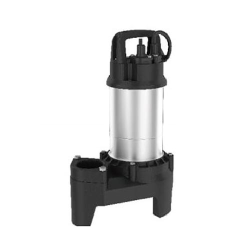
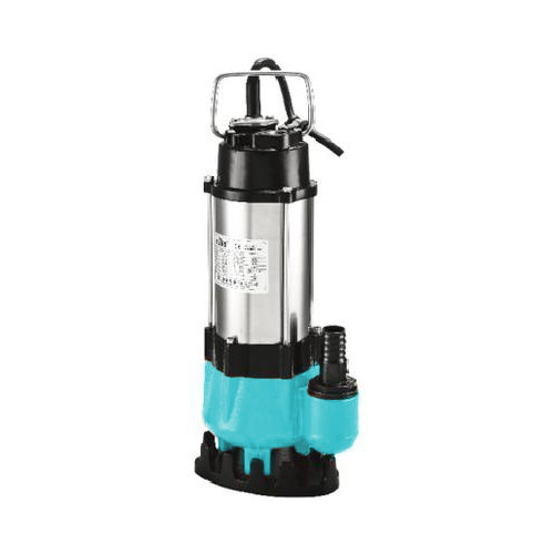
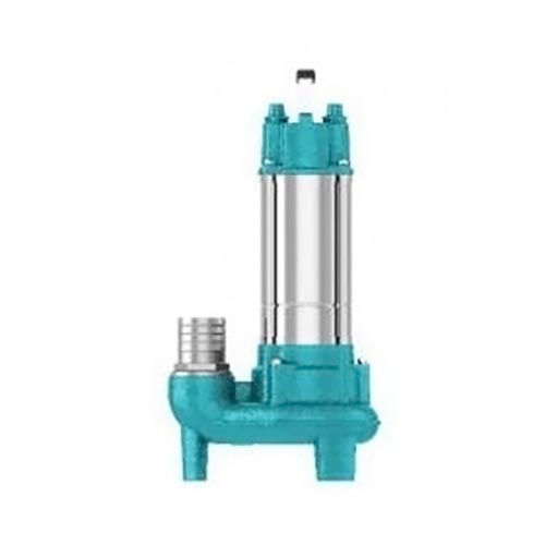
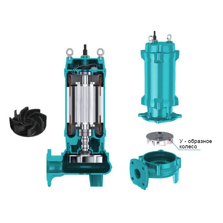


 stainless steel sewer pump")

