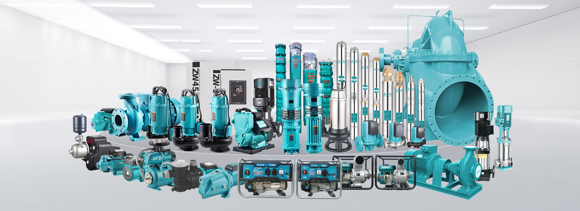

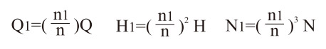
S Центробежный Насос С Разъемным Корпусом представляет собой одноступенчатый горизонтальный центробежный насос с двойным всасыванием, используемый для транспортировки чистой воды и жидкостей, как по физическим, так и по химическим свойствам схожих с водой, максимальная температура которых не должна превышать 80 ℃. Подходит для водоснабжения и водоотведения на заводах, шахтах, в городах и на электростанциях, для осушения заболоченных земель и орошения сельскохозяйственных угодий, а также для различных гидравлических проектов.
The pump S - type is a single -stage two -stage horizontal centrifugal pump of an average open type, designed to transport pure water and liquids with physical - chemical properties similar to water, at a maximum temperature of not more than 80 ° C and suitable for supply and drainage at factories, mines, in cities and power plants, drainage and irrigation of agricultural. land for various hydraulic operations.
The series pumps comply with the standards GB / T3216 and GB / T5657.
All entrances and outputs of the pump are located below the axis, horizontally and perpendicular to the axis, the pump housing opens in the middle, so there is no need to dismantle the input and source pipe and engine (or other primary engine). From the clutch point of view, the pump moves clockwise. The pump can also move counterclockwise, but special attention should be paid to the order.
The main components of the pump: the pump body (1), the pump cover (2), the impeller (3), the axis (4), the double absorbing sealing ring (5), the sleeve (6), the bearing (15), etc., except for the axis made of high -quality carbon steel, the rest are made of cast iron. This material can be replaced by other materials on different environments.
The pump housing and the pump cover form the impeller studio with threaded holes on the flanges of the entrance and exit for installing vacuum meters and pressure gauges, as well as for drainage under them.
The impeller is calibrated according to static equilibrium, fixed with the shell and nut of the casing on both sides, with the help of a nut, you can adjust its axial position and balance the axial force with a symmetrical location of the blades, the axial bearing can withstand residual axial power.
The pump axis is maintained by two single -row centrauming ball bearings, which are installed in the bearing housing at both ends of the pump and lubricated with lubrication. The double absorption sealing ring is used to reduce the leak on the impeller. The pump is controlled directly using an elastic coupling. (If a rubber drive is used, an additional support should be set).
The valve is a compaction of the filler, and for cooling and lubricating the airtight cavity and preventing air entering the pump between fillers there is a filler ring. During the operation of the pump, a small amount of water of high pressure enters the filler cavity through a conical beard and performs the function of a water shutter.
1. The assembly of the parts of the rotor: sequentially on the axis of the pump, a impeller, a sleeve, a tick nut, a stuffing box, an oilcopic ring, a salted seal, a mechanical seal, a mechanical seal, a water retaining ring and a bearing, and then a clutch.
2. Check the sealed outer ring of the impeller separately from the casing column of the rotor, the radial beating of which should not exceed the parameters indicated in the table below.
3. The rotor is installed on the pump housing, adjust the impeller so that its axial position is in the middle of the double absorbing sealing ring on both sides, then fix it, and then fix the bearing cover with a motionless screw.
| Nominal diameter | <50 | 50~120 | 120~250 | 250~500 | 500~800 | 800~1250 |
| Jumping ability | 0.03 | 0.04 | 0.05 | 0.06 | 0.08 | 0.10 |
4. Load the filler (if this is a compaction of the filler), a paper pad on the intermediate hole and the pump cover, first tighten the pine of the threaded tail cone, and then tighten the nut of the pump lid. Set the filler cover, but do not press it too tightly, otherwise the sleeve can heat up, leaving more energy; If a mechanical seal is used, adjust the ability to compress the mechanical seal to make sure that the leak does not occur.
After the assembly is completed, moving the pump axis by hand, it should be smooth and uniform and should not touch. Dismantling can be carried out in the opposite of the above.
1. Check if the pump and engine are damaged.
2. The height of the installation of the pump in combination with hydraulic losses of the suction pipeline and its speed of speed, i.e. NPSHA of the unit should be more than NPSHR. The size of the base must correspond to the size of the installation of the pump unit.
3. Installation procedure:
(1) Place the pump on the concrete foundation using the built -in the foundation bolt, adjust the horizontal by adjusting the wedge laying and correctly tighten the bolt to prevent the bolt displacement.
(2) Pour concrete between the foundation and the feet of the pump.
(3) After the concrete solidification, tighten the underground legs bolts, once again check the horizontality of the pump.
(4) Correct the concentricity between the pump and the axis of the engine so that it is on a straight line. The permissible admission to different centricity of the external rings of the two clutches is 0.1 mm, while the gap between one end and uneven around the circumference is 0.3 mm (another amendment should also meet the above requirements after the connection and commissioning of the water supply).
(5) After determining the direction of rotation of the engine corresponding to the direction of rotation of the pump, the clutch pin pin is installed.
4. Pipelines for feed and output should be supported by separate supports, and not the pump body.
5. The connection between the pump and the pipeline should maintain good tightness, especially the input pipeline, which should be guaranteed without air leakage and cannot be built into the unit.
6. As a rule, if the pump is installed above the water level in the water intake, you can install the lower valve to start the pump and water injection, as well as use a vacuum pump to drain water.
7. The output pipes of the pumps, as a rule, require the installation of a valve and a lock valve (a rise less than 20 m does not require installation), and the check valve is installed behind the valve.
The mentioned mentioned method of installation refers to pumps that do not have a social basis.
For pumps with a conventional foundation between the foundation and concrete, a wedge -shaped iron gasket is used to correct the unit level, and then concrete is cemented between them. The principle of installation and requirements are identical to pumps that do not have a common basis.
1. Starting and stopping
(1) Before starting the rotor of the moving pump, the rotor senses should be light, smooth, uniform.
(2) Close the exhaust valve and fill the water with a pump (in the absence of the lower valve, the water is pumped out with a vacuum pump for the direction of water). Make sure that the pump is filled with water and does not have access to the air.
(3) Before starting the engine, first turn off the vacuum or manometer fork, if it is installed on the pump, connect to the pump, and then turn on the fork when the engine moves at normal speed; Then the output valve gradually opens, reducing it at a larger consumption or, conversely, increasing or increasing it.
(4) Evenly tighten the pressure nut on the filler cover to prevent drops of drops and pay attention to the increase in temperature outside the filler cavity.
(5) When the pump stops, first turn off the fork of a vacuum or manometer and a valve on the water supply, and then turn off the engine power. At a low ambient temperature, open the square plug under the pump housing and drain residual water to prevent ice cracks.
(6) During a long stop, remove the pump and dry the parts and apply anti -corrosion fat to the treated surface.
2. Running
(1) The maximum temperature of the pump bearing should not exceed 75 ° C
(2) The volume of lubricants based on calcium for lubricant bearings is suitable for maintaining 1/3 - 1 /2 of the spaces in bearings.
(3) If the lid’s lid is slightly worn out, then the lid of the oil seal should be properly pressed, and if the wear is too large, then the lid of the oil seal should be replaced.
(4) regularly check elastic clutch and pay attention to increasing the temperature of the engine bearings.
(5) During work, when noise or other unusual sounds is heard, you should stop immediately to find out the cause and eliminate it.
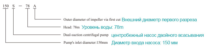
(6) Do not increase the pump speed arbitrarily, but you can reduce the speed of the pump. For example, for this type of pumps, the rated speed of rotation n, the consumption of Q, the pressure H, the power of the axis N, the reduced speed N1, the consumption, the pressure and power of the axis after a decrease in the velocity are Q1, H1 and N1, respectively. The transformation is carried out according to the following formula.
| Failure | Cause | troubleshooting |
| 1. The pump does not suck in water, it greatly jumps the pressure indicator and vacuummeter |
1. Wooded water is insufficient; 2. The leak comes from the pipeline or counter. |
1. Pour more water; 2. Tighten or block the place of leakage. |
| 2. The pump does not suck water, a high vacuum is displayed on the vacuum. |
1. The receiving valve is not open or locked; 2. The resistance of the suction pipeline is too much; 3. Too high the height of water absorption |
1. Correct or replace the bottom valve; 2. Rinse or replace the pipeline; 3. Reduce height |
| 3. Water does not leave the pump, the pressure is displayed on the pressure gauge. |
1. Too high resistance to the exhaust pipeline of water; 2. Incorrect direction of rotation; 3. The impeller is blocked; 4. Insufficient speed of rotation. |
1. Check or shorten the pipeline; 2. Correct the direction of engine rotation 3. Take it off; 4. Check the supply voltage and increase the speed |
| 4. Insufficient consumption or too low pressure. |
1. A working wheel or both intake and final water pipelines is closed 2. There is too much wear due to the sealing ring of double absorption or damage to the working wheel; 3. The rotation speed is below the given value. |
1. Clean the working wheel or pipeline; 2. Replace it; 3. Adjust it to a nominal value. |
| 5. too much consumption of power by the pump |
1. The packaging is pressed too tightly; 2. Friction between the working wheel and the sealing ring of double absorption; 3. The consumption is too large. |
1. Weaken it; 2. Check the reason to eliminate it; 3. Reduce the opening of the valve |
| Failure | Cause | troubleshooting |
| 6. An unusual sound inside the pump, water does not enter the pump. |
1. The resistance of the suction pipeline is too much; 2. Too high absorption height; 3. The air is sucked into the water suction site 4. The temperature is too high when sucking in the liquid; 5. The loss of steam occurs due to too much consumption. |
1. Prepare the suction pipeline and the lower valve; 2. Lower it; 3. Check the bottom valve, reduce the height of the suction, block the place of air leakage; 4. Mount it; 5. Adjust the exhaust gate for water so that it works in the set performance range. |
| 7. Abnormal vibration of the pump. |
1. In this case, steam loss takes place; 2. The working wheel is not balanced; 3. The axis of the pump and engine are not concentric; 4. The hairpin on the leg weakened |
1. Adjust the valve to work in a given performance range; 2. Take a static amendment for the working wheel; 3. Correct concentricity 4. Tighten it |
| 8. The bearing has overheated |
1. Non -oil lack of inside; 2. The axis of the pump and engine are not on the same central line |
1. Check and clean the bearing housing, grease it; 2. Correct concentricity so that both be on the same central line. |
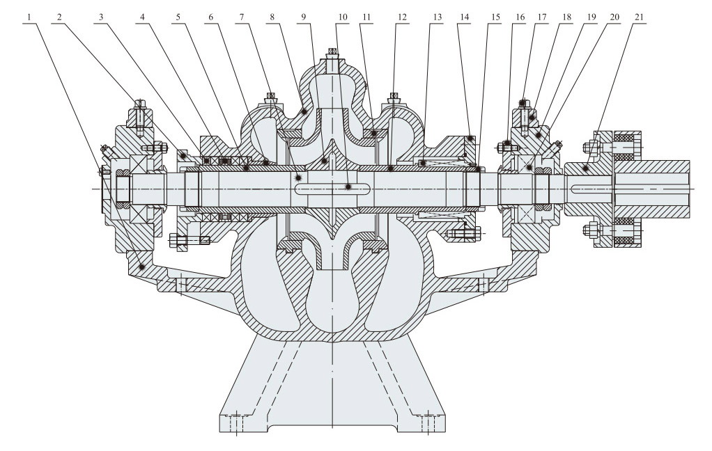
| 1 | Pump body | 2 | Salnic stuffing | 3 | Package | 4 | Sealing ring | 5 | Packaging coupling | 6 | Packing sleeve | 7 | Shaft |
| 8 | Pump cover | 9 | Working wheel | 10 | Key |
11 | Double absorption ring | 12 | Muffle with a mechanical seal | 13 | Mechanical printing | 14 | Mechanical sealing oil seal |
| 15 | Gaet of the coupling | 16 | Bearing oil seal | 17 | Fastener screw | 18 | Bearing body oil seal | 19 | Bearing case | 20 | Single -post centraeting ball bearing | 21 | Grab |
| Type of pump | Consumption Q. | Head (m) |
speed (r/min) |
Power (KW) | Efficiency % |
(NPSH)r (m) |
Weight (kg) |
||
| (m³/h) | (L/s) | The power of the shaft |
Engine | ||||||
| 150S-100 |
120 160 192 |
33.3 44.4 53.3 |
103 100 92 |
2950 |
48.8 59.7 67.7 |
75 |
69 73 71 |
4.5 | 168 |
| 150S-78 |
126 160 198 |
35.0 44.4 55.0 |
84 78 70 |
2950 |
41.2 45.9 53.1 |
55 |
70 74 71 |
4.5 | 158 |
| 150S-78A |
112 140 180 |
31.1 39 50.0 |
65 60 53.5 |
2950 |
29.1 31.8 37.5 |
45 |
68 72 70 |
4.5 | 158 |
| 150S-50 |
130 160 220 |
36.1 44.4 61.1 |
52 50 40 |
2950 |
25.2 27.6 31.5 |
37 |
73 79 76 |
4.5 | 147 |
| 150S-50A |
112 140 180 |
31.1 38.9 50.0 |
42 39 34 |
2950 |
18.3 19.8 22.8 |
30 |
70 75 73 |
4.5 | 147 |
| 150S-50B |
108 133 160 |
30.0 36.9 44.4 |
38 36 32 |
2950 |
16.9 18.4 19.4 |
22 |
66 71 72 |
4.5 | 147 |
| 200S-95 |
200 280 324 |
55.6 77.8 90.0 |
102 95 85 |
2950 |
81.7 94.0 100.0 |
132 |
68 77 75 |
5 | 240 |
| 200S-95A |
180 268 310 |
50.0 74.4 86.1 |
95 87 78 |
2950 |
71.6 84.6 90.2 |
110 |
65 75 73 |
5 | 240 |
| 200S-95B |
165 245 298 |
45.8 68.1 82.8 |
81 72 60 |
2950 |
56.4 64.9 69.5 |
75 |
64.5 74 70 |
5 | 240 |
| 200S-63 |
216 280 351 |
60.0 77.8 97.5 |
70.4 63 52 |
2950 |
55.9 59.3 69.0 |
75 |
74 81 72 |
5 | 187 |
| 200S-63A |
186 270 332 |
51.7 75.0 92.2 |
56.5 48 38.5 |
2950 |
41.5 45.8 49.0 |
55 |
69 77 71 |
5 | 187 |
| 200S-42 |
216 280 342 |
60.0 77.8 95.0 |
48 42 35 |
2950 |
35.3 37.7 41.0 |
45 |
80 85 79.5 |
5 | 219 |
| 200S-42A |
198 270 310 |
55.0 75.0 86.1 |
43 36 31 |
2950 |
31.3 33.1 34.6 |
37 |
74 80 75.5 |
5 | 219 |
| 250S-65 |
360 485 612 |
100.0 134.7 170.0 |
70 65 54 |
1480 |
91.5 108.6 127.6 |
132 |
75 79 70.5 |
3.8 | 518 |
| 250s-65A |
300 420 535 |
83.3 116.7 148.6 |
53 48 40 |
1480 |
61.8 71.3 79.8 |
90 |
70 77 73 |
3.8 | 518 |
| 250S-39 |
360 485 612 |
100.0 134.7 170.0 |
43 39 32.5 |
1480 |
55.4 62.0 69.4 |
75 |
76 83 78 |
3.8 | 400 |
| 250s-39a |
324 420 576 |
90.0 116.7 160.0 |
31.5 29 22 |
1480 |
38.6 42.5 48.6 |
55 |
72 78 71 |
3.8 | 400 |
| 250S-24 |
360 485 576 |
100.0 134.7 160.0 |
27 24 19 |
1480 |
33.1 36.8 36.3 |
45 |
80 86 82 |
3.8 | 305 |
| 250S-24A |
342 420 482 |
95.0 116.7 133.9 |
22 20 17 |
1480 |
25.9 27.6 27.9 |
37 |
79 83 80 |
3.8 | 305 |
| 250S-14 |
360 485 576 |
100.0 134.7 160.0 |
14 11 |
1480 |
20.8 21.7 22.1 |
30 |
80 85 78 |
3.8 | 305 |
| 250S-14A |
320 420 505 |
88.9 116.7 140.3 |
10 12 10 8.2 |
1480 |
13.2 14.1 14.5 |
18.5 |
79 81 78 |
3.8 | 305 |
| Type of pump | Consumption Q. | Head (m) |
Speed (r/min) |
Power (KW) | Efficiency % |
(NPSH)r (m) |
Weight (kg) |
||
| (m³/h) | (L/s) | The power of the shaft | Engine | ||||||
| 300S-90 |
590 790 936 |
163.9 219.4 260.0 |
95 90 86 |
1480 |
224.4 251.4 277.4 |
315 |
68 77 79 |
4.8 | 950 |
| 300S-90A |
576 756 918 |
160.0 210.0 255.0 |
83 78 72 |
1480 |
200.2 216.9 239.9 |
280 |
65 74 75 |
4.8 | 950 |
| 300S-90B |
546 720 900 |
151.7 200.0 250.0 |
72 67 57 |
1480 |
169.9 185.0 194.0 |
220 |
63 71 72 |
4.8 | 950 |
| 300S-58 |
576 790 972 |
160.0 219.4 270.0 |
65 58 50 |
1480 |
135.9 148.5 165.4 |
185 |
75 84 80 |
4.8 | 599 |
| 300S-58A |
529 735 893 |
146.9 204.2 248.1 |
55 50 42 |
1480 |
110.0 122.0 129.2 |
160 |
72 82 79 |
4.8 | 599 |
| 300S-58B |
504 685 835 |
140.0 190.3 231.9 |
47.2 43 37 |
1480 |
91.2 100.2 109.2 |
132 |
71 80 77 |
4.8 | 599 |
| 300S-32 |
612 790 900 |
170.0 219.4 250.0 |
36.5 32 27.3 |
1480 |
74.2 79.1 83.6 |
90 |
82 87 80 |
4.8 | 709 |
| 300S-32A |
537 700 790 |
149.2 194.4 219.4 |
29 26 22.5 |
1480 |
53.7 59.0 62.0 |
75 |
79 84 78 |
4.8 | 709 |
| 300S-19 |
612 790 935 |
170.0 219.4 259.7 |
22 19 15.5 |
1480 |
45.8 48.4 52.6 |
55 |
80 84.5 75 |
4.8 | 434 |
| 300S-19A |
485 700 798 |
134.7 194.4 221.7 |
18 15 13 |
1480 |
32.1 35.7 37.2 |
45 |
74 80 76 |
4.8 | 434 |
| 300S-12 |
612 790 900 |
170.0 219.4 250.0 |
14.5 12 10 |
1480 |
30.2 31.1 33.1 |
37 |
80 83 74 |
4.8 | 413 |
| 300S-12A |
515 700 785 |
143.1 194.4 218.1 |
11.5 10 9 |
1480 |
22.4 24.4 25.6 |
30 |
72 78 75 |
4.8 | 413 |
| 350S-125 |
850 1260 1660 |
236.1 350.0 461.1 |
135 125 110 |
1480 |
446.3 542.7 685.6 |
710 |
70 79 72.5 |
5.5 | 1580 |
| 350S-125A |
787 1181 1550 |
218.6 328.1 430.6 |
121 112 100 |
1480 |
381.2 461.6 594.3 |
630 |
68 78 71 |
5.5 | 1580 |
| 350S-125B |
700 1098 1350 |
194.4 305.0 375.0 |
104 96 89 |
1480 |
300.3 372.7 448.0 |
500 |
66 77 73 |
5.5 | 1580 |
| 350S-75 |
972 1260 1440 |
270.0 350.0 400.0 |
80 75 69 |
1480 |
264.6 302.6 329.9 |
355 |
80 85 82 |
5.5 | 1200 |
| 350s-75a |
900 1170 1332 |
250.0 325.0 370.0 |
70 65 60 |
1480 |
219.9 252.5 275.4 |
315 |
78 82 79 |
5.5 | 1200 |
| 350s-75B |
800 1080 1200 |
222.2 300.0 333.3 |
60 55 52 |
1480 |
174.2 204.7 220.6 |
280 |
75 79 77 |
5.5 | 1200 |
| 350S-44 |
972 1260 1476 |
270.0 350.0 410.0 |
50 44 37 |
1480 |
163.3 177.6 188.2 |
220 |
81 85 79 |
5.5 | 1105 |
| 350S-44A |
876 1116 1360 |
243.3 310.0 377.8 |
41 36 30 |
1480 |
123.8 131.8 140.6 |
160 |
79 83 79 |
5.5 | 1105 |
| 350S-26 |
972 1260 1440 |
270.0 350.0 400.0 |
29 26 22 |
1480 |
93.6 101.3 102.7 |
132 |
82 88 84 |
5.5 | 672 |
| Type of pump | Consumption Q. | Head (m) |
Speed (r/min) |
Power (KW) | Efficiency % |
(NPSH)r (m) |
Weight (kg) |
||
| (m³/h) | (L/s) | The power of the shaft | Engine | ||||||
| 350s-26A |
840 1130 1260 |
233.3 313.9 350.0 |
24 21 19 |
1480 |
70.4 77.8 81.5 |
90 |
78 83 80 |
5.5 | 672 |
| 350S-16 |
960 1260 1440 |
266.7 350.0 400.0 |
19.5 16 13 |
1480 |
61.4 63.8 67.9 |
75 |
83 86 75 |
5.5 | 632 |
| 350S-16A |
800 1130 1340 |
222.2 313.9 372.2 |
15 12 9.5 |
1480 |
42.4 45.6 48.1 |
55 |
77 81 72 |
5.5 | 632 |
| 400S-90 |
1140 1620 1980 |
316.7 450.0 550.0 |
102 90 78 |
1480 |
403.2 461.5 512.7 |
560 |
78.5 86 82 |
7.9 | 1450 |
| 400S-90A |
1020 1460 1850 |
283.3 405.6 5139 |
89 78 66 |
1480 |
320.9 369.1 415.5 |
450 |
77 84 80 |
7.9 | 1450 |
| 400S-90B |
960 1330 1720 |
266.7 369.4 477.8 |
78 68 56 |
1480 |
268.2 300.2 336.2 |
400 |
76 82 78 |
7.9 | 1450 |
| 400S-40 |
800 1080 1320 |
222.2 300.0 366.7 |
45 40 32 |
970 |
124.1 140.0 149.3 |
185 |
79 84 77 |
4.9 | 1800 |
| 400S-40A |
720 960 1150 |
200.0 266.7 319.4 |
39.5 35 29.5 |
970 |
100.5 111.5 121.5 |
160 |
77 82 76 |
4.9 | 1800 |
| 500S-98 |
1620 2020 2340 |
450.0 561.1 650.0 |
104.5 98 92 |
970 |
598.5 673.6 741.8 |
800 |
77 80 79 |
6 | 2360 |
| 500S-98A |
1500 1872 2170 |
416.7 520.0 602.8 |
88 83 77 |
970 |
479.1 535.4 583.1 |
630 |
75 79 78 |
6 | 2360 |
| 500S-98B |
1400 1746 2020 |
388.9 485.0 561.1 |
79 74 71 |
970 |
401.4 448.1 500.5 |
560 |
75 78.5 78 |
6 | 2360 |
| 500S-59 |
1620 2020 2340 |
450.0 561.1 650.0 |
64 59 53 |
970 |
357.3 390.9 422.0 |
450 |
79 83 80 |
6 | 2150 |
| 500S-59A |
1500 1872 2170 |
416.7 520.0 602.8 |
53 49 45 |
970 |
288.6 316.1 345.2 |
400 |
75 79 77 |
6 | 2150 |
| 500S-59B |
1400 1746 2020 |
388.9 485.0 561.1 |
43 40 36.5 |
970 |
227.6 250.2 267.6 |
315 |
72 76 75 |
6 | 2150 |
| 500S-35 |
1620 2020 2340 |
450.0 561.1 650.0 |
40 35 30.5 |
970 |
207.5 218.7 228.6 |
280 |
85 88 85 |
6 | 1600 |
| 500S-35A |
1400 1746 2020 |
388.9 485.0 561.1 |
30 27 24 |
970 |
139.4 151.0 159.0 |
220 |
82 85 83 |
6 | 1600 |
| 500S-22 |
1620 2020 2340 |
450.0 561.1 650.0 |
24.5 22 19.4 |
970 |
136.8 144.0 145.4 |
160 |
79 84 85 |
6 | 1722 |
| 500S-22A |
1400 1746 2020 |
388.9 485.0 561.1 |
19 17 15 |
970 |
97.9 101.0 101.8 |
132 |
74 80 81 |
6 | 1722 |
| 500S-13 |
1620 2020 2340 |
450.0 561.1 650.0 |
15 13 10 |
970 |
82.7 86.1 81.7 |
110 |
80 83 78 |
6 | 1730 |
| 600S-100 |
2160 3170 3600 |
600.0 880.6 1000.0 |
110 100 92 |
970 |
829.2 1015.2 1073.3 |
1400 |
78 85 84 |
6 | 7200 |
| 600S-100A |
1980 3000 3240 |
550.0 833.3 900.0 |
100 90 85 |
970 |
700.0 875.0 914.3 |
1120 |
77 84 82 |
6 | 7200 |
| Type of pump | Consumption Q. | Head (m) |
Speed (r/min) |
Power (KW) | Efficiency % |
(NPSH)r (m) |
Weight (kg) |
||
| (m³/h) | (L/s) | The power of the shaft | Engine | ||||||
| 600S-100B |
1800 2830 3060 |
500.0 786.1 850.0 |
90 80 75 |
970 |
588.0 751.6 780.9 |
1000 |
75 82 80 |
6 | 7200 |
| 600S-75 |
2160 3170 3600 |
600.0 880.6 1000.0 |
84 75 68 |
970 |
633.2 761.4 802.9 |
900 |
78 85 83 |
7.5 | 2600 |
| 600S-75A |
1980 2880 3240 |
550.0 800.0 900.0 |
68 62 58 |
970 |
488.7 607.6 655.8 |
800 |
75 80 78 |
7.5 | 2600 |
| 600S-75B |
1750 2650 3150 |
486.1 736.1 875.0 |
60 55 50 |
970 |
408.3 508.7 579.4 |
630 |
70 78 74 |
7.5 | 2600 |
| 600S-47 |
2160 3170 3600 |
600.0 880.6 1000.0 |
54 47 43 |
970 |
401.9 460.9 507.7 |
560 |
79 88 83 |
7.5 | 2800 |
| 600S-47A |
1980 2920 3240 |
550.0 811.1 900.0 |
45 40 37 |
970 |
311.0 369.7 398.0 |
450 |
78 82 |
7.5 | 2800 |
| 600S-32 |
2160 3170 3600 |
600.0 880.6 1000.0 |
36 32 29 |
970 |
271.4 313.8 334.4 |
400 |
78 88 85 |
7.5 | 2300 |
| 600S-32A |
2000 2880 3240 |
555.6 800.0 900.0 |
30 27 25 |
970 |
214.9 246.1 262.5 |
280 |
76 86 84 |
7.5 | 2300 |
| 600S-32B |
1800 2628 3000 |
500.0 730.0 833.3 |
24.5 22 20 |
970 |
164.5 187.4 199.2 |
250 |
73 84 82 |
7.5 | 2300 |
| 600S-22 |
2520 3170 3600 |
700.0 880.6 1000.0 |
25 22 19 |
970 |
204.2 215.7 227.1 |
250 |
84 88 82 |
7 | 2300 |
| 600S-22A |
2160 2880 3240 |
600.0 800.0 900.0 |
21 18 16 |
970 |
152.4 162.2 170.0 |
185 |
81 87 83 |
7 | 2300 |
| 800S-22 |
4320 5500 6480 |
1200.0 1527.8 1800.0 |
25 22 19 |
730 |
358.5 370.1 389.7 |
450 |
82 89 86 |
7 | 3800 |
|
3000 4400 5040 |
8333 1222.2 1400.0 |
16 14 12.5 |
585 |
163.3 190.6 201.8 |
250 |
80 88 85 |
5 | 3800 | |
| 800S-22A |
3960 4830 5500 |
1100.0 1341.7 1527.8 |
19 17 15 |
730 |
246.8 254.0 261.1 |
315 |
83 88 86 |
7 | 3800 |
|
2800 3870 4500 |
777.8 1075.0 1250.0 |
12.5 11 9.5 |
585 |
119.1 133.2 138.5 |
185 |
80 87 84 |
5 | 3800 | |
| 800S-32 |
4320 5500 6480 |
1200.0 1527.8 1800.0 |
35 32 29 |
730 |
502.0 538.3 588.0 |
630 |
82 89 87 |
7 | 4900 |
|
3000 4400 5200 |
833.3 12222 1444.4 |
23 20 17 |
585 |
234.8 272.2 283.1 |
315 |
80 88 85 |
4.5 | 4900 | |
| 800S-32A |
3500 4950 6000 |
972.2 1375.0 1666.7 |
29.5 26 23 |
730 |
351.3 398.1 436.8 |
500 |
80 88 86 |
7 | 4900 |
|
2700 3960 4680 |
750.0 1100.0 1300.0 |
19 16.5 14 |
585 |
174.6 204.4 212.3 |
250 |
80 87 84 |
4.5 | 4900 | |
| 800S-47 |
4320 5500 6480 |
1200.0 1527.8 1800.0 |
51 47 42 |
730 |
722.6 781.9 841.9 |
1000 |
83 90 88 |
6.5 | 5000 |
|
3000 4400 5200 |
833.3 1222.2 1444.4 |
35 30 26 |
585 |
357.3 403.7 428.0 |
500 |
80 89 86 |
4 | 5000 | |
| 800s-47a |
3500 5070 6000 |
972.2 1408.3 1666.7 |
45 40 36 |
730 |
529.3 620.3 683.7 |
710 |
81 89 86 |
6.5 | 5000 |
|
2800 4060 4800 |
777.8 1127.8 1333.3 |
30 25 22 |
585 |
285.8 314.0 334.3 |
355 |
80 88 86 |
4 | 5000 | |
| Type of pump | Consumption Q. |
Head (m) |
Speed (r/min) |
Power (KW) | Efficiency % |
(NPSH)r (m) |
Weight (kg) |
||
| (m³/h) | (L/s) | The power of the shaft | Engine | ||||||
| 800S-70 |
6100 8100 9300 |
1694.4 2250.0 2583.3 |
90 83 75 |
730 |
1868.1 2153.1 2260.4 |
2500 |
80 85 84 |
9 | 8000 |
| 800S-70A |
5800 7700 8800 |
1611.1 2138.9 2444.4 |
82 75 68.5 |
730 |
1628.5 1871.5 2001.2 |
2240 |
79.5 84 82 |
9 | 8000 |
| 800S-70B |
5500 7300 8400 |
1527.8 2027.8 2333.3 |
73.5 68 62 |
730 |
1393.0 1628.1 1772.2 |
1800 |
79 83 80 |
9 | 8000 |
| 800S-76 |
4000 5500 6500 |
1111.1 1527.8 1805.6 |
80 76 71 |
730 |
1102.7 1293.1 1444.0 |
1600 |
79 88 87 |
6 | 7550 |
|
3000 4400 5500 |
833.3 1222.2 1527.8 |
54 49 43 |
585 |
551.3 674.6 757.4 |
800 |
80 87 85 |
4 | 7550 | |
| 800S-76A |
3500 5080 6000 |
972.2 1411.1 1666.7 |
69 65 61 |
730 |
832.2 1033.2 1186.1 |
1250 |
79 87 84 |
6 | 7550 |
|
2800 4070 5000 |
777.8 1130.6 1388.9 |
46.5 42 37 |
585 |
448.6 541.1 606.8 |
630 |
79 86 83 |
4 | 7550 | |
| 800S-76B |
3000 4680 5500 |
833.3 1300.0 1527.8 |
59 55 51 |
730 |
642.4 824.4 920.0 |
1000 |
75 85 83 |
6 | 7550 |
|
2500 3750 4500 |
694.4 1041.7 1250.0 |
39 35 31 |
585 |
349.2 425.3 468.8 |
500 |
76 84 81 |
4 | 7550 | |
| 800S-105 |
3850 5500 6600 |
1069.4 1527.8 1833.3 |
110 105 100 |
730 |
1441.1 1807.0 2089.1 |
2500 |
80 87 86 |
6.5 | 8000 |
| 900S-23 |
6200 8280 9432 |
1722.2 2300.0 2620.0 |
28 23 19.5 |
730 |
590.7 602.8 610.6 |
710 |
80 86 82 |
9.3 | 6000 |
| 1000S-36 |
7920 9900 11380 |
2200.0 2750.0 3161.1 |
40 36 33 |
495 |
1039.0 1102.5 1202.7 |
1250 |
83 88 85 |
7.8 | 13000 |
| 1200S-24 |
8400 12000 14400 |
2333.3 3333.3 4000.0 |
28 24 18.5 |
590 |
748.8 901.1 906.5 |
1250 |
85.5 87 80 |
7.7 | 9000 |
| 1200S-39 |
7200 9000 10800 |
2000.0 2500.0 3000.0 |
42.5 39 33 |
500 |
1015.9 1085.8 1155.0 |
1250 |
82 88 84 |
5.5 | - |
| 1200s-39a |
6480 8100 9720 |
1800.0 2250.0 2700.0 |
38.5 35 29.5 |
500 |
848.9 892.2 940.4 |
1120 |
80 86.5 83 |
5.5 | - |
| 1200s-39B |
5832 7290 8748 |
1620.0 2025.0 2430.0 |
34 31 26 |
500 |
674.7 715.3 755.1 |
900 |
80 86 82 |
5.5 | - |
| 1200S-56 |
8640 10800 12960 |
2400.0 3000.0 3600.0 |
60 56 49 |
600 |
1721.0 1870.9 2033.8 |
2240 |
82 88 85 |
7.5 | - |
| 1200S-56A |
7776 9720 11664 |
2160.0 2700.0 3240.0 |
54 50 42 |
600 |
1411.2 1520.7 1606.7 |
2000 |
81 87 83 |
7.5 | - |
| 1200S-56B |
7000 8750 10500 |
1944.4 2430.6 2916.7 |
48 44 3/27 |
600 |
1143.3 1218.7 1289.7 |
1600 |
80 86 82 |
7.5 | - |
| 1200S-76 |
8640 10800 12960 |
2400.0 3000.0 3600.0 |
81.5 76 65 |
730 |
2216.0 2482.7 2620.8 |
2800 |
86.5 90 87.5 |
9 | 13000 |
| 1200S-76A |
7776 9720 11664 |
2160.0 2700.0 3240.0 |
6a 0+ 55 |
730 |
1703.5 1924.4 2054.5 |
2240 |
84.5 88 85 |
9 | 13000 |
| 1200S-76B |
7000 8750 10500 |
1944.4 2430.6 2916.7 |
55 52 45 |
730 |
1270.4 1440.2 1531.3 |
1600 |
82.5 86 84 |
9 | 13000 |
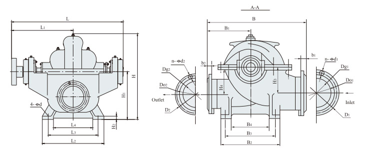
| Type | The dimensions of the pump figure | The dimensions of the input flange | The dimensions of the output flange | |||||||||||||||||||||||||
| L | L1 | L2 | L3 | L4 | B | B1 | B2 | B3 | B3 ' | B4 | B4 ' | H | H1 | H2 | H3 | H4 | 4-φd | Dg1 | Do1 | D1 | B1 | n-φd1 | DG2 | Do2 | D2 | B2 | n-φd2 | |
| 150S-100 | 740.5 | 410 | 330 | 280 | 190 | 550 | 250 | 330 | 280 | — | 190 | — | 490 | 285 | 25 | 140 | 170 | 4-F18 | 150 | 240 | 285 | 26 | 8-F23 | 100 | 180 | 220 | 24 | 8-F19 |
| 150S-78 | 713.5 | 397 | 330 | 280 | 190 | 550 | 250 | 330 | 280 | — | 190 | — | 472.5 | 285 | 25 | 140 | 155 | 4-F18 | 150 | 240 | 285 | 26 | 8-F23 | 100 | 180 | 220 | 24 | 8-F19 |
| 150S-78A | ||||||||||||||||||||||||||||
| 150S-50 | 713.5 | 397 | 330 | 280 | 190 | 550 | 250 | 330 | 280 | — | 190 | — | 455 | 285 | 25 | 140 | 140 | 4-F18 | 150 | 240 | 285 | 26 | 8-F23 | 100 | 180 | 220 | 24 | 8-F19 |
| 150S-50A | ||||||||||||||||||||||||||||
| 150S-50B | ||||||||||||||||||||||||||||
| 200S-95 | 850.5 | 475 | 330 | 280 | 190 | 680 | 330 | 330 | 280 | — | 190 | — | 555 | 355 | 25 | 170 | 170 | 4-F18 | 200 | 295 | 340 | 24 | 8-F23 | 125 | 210 | 250 | 22 | 8-F19 |
| 200S-95A | ||||||||||||||||||||||||||||
| 200S-95B | ||||||||||||||||||||||||||||
| 200S-63 | 743.5 | 409 | 330 | 280 | 190 | 620 | 300 | 330 | 280 | — | 190 | — | 547 | 355 | 25 | 170 | 170 | 4-F18 | 200 | 295 | 340 | 24 | 8-F23 | 150 | 240 | 285 | 24 | 8-F23 |
| 200S-63A | ||||||||||||||||||||||||||||
| 200S-42 | 743.5 | 409 | 330 | 280 | 190 | 620 | 300 | 330 | 280 | — | 190 | — | 547 | 355 | 25 | 170 | 170 | 4-F18 | 200 | 295 | 340 | 24 | 8-F23 | 150 | 240 | 285 | 24 | 8-F23 |
| 200S-42A | ||||||||||||||||||||||||||||
| 250S-65 | 1100.5 | 612 | 510 | 450 | 330 | 880 | 400 | 620 | 550 | — | 430 | — | 856 | 510 | 40 | 240 | 300 | 4-F27 | 250 | 350 | 395 | 28 | 12-F23 | 150 | 240 | 285 | 26 | 8-F23 |
| 250s-65A | ||||||||||||||||||||||||||||
| 250S-39 | 983.5 | 549 | 410 | 350 | 230 | 890 | 440 | 510 | 450 | — | 330 | — | 750 | 450 | 30 | 200 | 260 | 4-F27 | 250 | 350 | 395 | 28 | 12-F23 | 200 | 295 | 340 | 26 | 8-F23 |
| 250s-39a | ||||||||||||||||||||||||||||
| 250S-24 | 983.5 | 517 | 410 | 350 | 230 | 850 | 400 | 510 | 450 | — | 330 | — | 738 | 4450 | 30 | 210 | 215 | 4-F27 | 250 | 350 | 395 | 28 | 12-F23 | 200 | 295 | 340 | 26 | 8-F23 |
| 250S-24A | ||||||||||||||||||||||||||||
| 250S-14 | 892.5 | 485 | 410 | 350 | 230 | 745 | 330 | 510 | 450 | — | 330 | — | 709 | 450 | 30 | 210 | 215 | 4-F27 | 250 | 350 | 395 | 28 | 12-F23 | 200 | 295 | 340 | 26 | 8-F23 |
| 250S-14A | ||||||||||||||||||||||||||||
| Type | The dimensions of the pump figure | The dimensions of the input flange | The dimensions of the output flange | |||||||||||||||||||||||||
| L | L1 | L2 | L3 | L4 | B | B1 | B2 | B3 | B3 ' | B4 | B4 ' | H | H1 | H2 | H4 | 4-φd | Dg1 | Do1 | D1 | B1 | n-φd1 | DG2 | Do2 | D2 | B2 | n-φd2 | ||
| 300S-90 | 1185 | 660 | 510 | 450 | 330 | 1046 | 470 | 620 | 550 | — | 420 | — | 898 | 510 | 40 | 268 | 325 | 4-F27 | 300 | 400 | 440 | 28 | 12-F23 | 200 | 295 | 340 | 26 | 8-F23 |
| 300S-90A | ||||||||||||||||||||||||||||
| 300S-90B | ||||||||||||||||||||||||||||
| 300S-58 | 1140 | 630 | 510 | 450 | 330 | 1070 | 530 | 620 | 550 | — | 430 | — | 852 | 510 | 40 | 240 | 310 | 4-F27 | 300 | 400 | 445 | 28 | 12-F23 | 250 | 350 | 395 | 28 | 12-F23 |
| 300S-58A | ||||||||||||||||||||||||||||
| 300S-58B | ||||||||||||||||||||||||||||
| 300S-32 | 1100 | 605 | 510 | 450 | 330 | 880 | 410 | 620 | 550 | — | 430 | — | 824 | 510 | 40 | 260 | 270 | 4-F27 | 300 | 400 | 445 | 28 | 12-F23 | 250 | 350 | 395 | 28 | 12-F23 |
| 300S-32A | ||||||||||||||||||||||||||||
| 300S-19 | 978.5 | 537 | 510 | 450 | 330 | 900 | 400 | 620 | 550 | — | 430 | — | 808 | 510 | 40 | 250 | 260 | 4-F27 | 300 | 400 | 445 | 28 | 12-F23 | 250 | 350 | 395 | 28 | 12-F23 |
| 300S-19A | ||||||||||||||||||||||||||||
| 300S-12 | 1009 | 552 | 510 | 450 | 330 | 1000 | 500 | 620 | 550 | — | 430 | — | 808 | 510 | 40 | 265 | 265 | 4-F27 | 300 | 400 | 445 | 28 | 12-F23 | 300 | 400 | 445 | 28 | 12-F23 |
| 300S-12A | ||||||||||||||||||||||||||||
| 350S-125 | 1431 | 801 | 580 | 500 | 360 | 1210 | 550 | 680 | 600 | — | 450 | — | 1080 | 620 | 50 | 330 | 410 | 4-F34 | 350 | 460 | 505 | 30 | 16-F23 | 200 | 295 | 340 | 26 | 12-F23 |
| 350S-125A | ||||||||||||||||||||||||||||
| 350S-125B | ||||||||||||||||||||||||||||
| 350S-75 | 1272 | 710 | 600 | 500 | 360 | 1250 | 600 | 690 | 600 | — | 450 | — | 1017 | 620 | 50 | 274 | 356 | 4-F34 | 350 | 460 | 505 | 30 | 16-F23 | 250 | 350 | 395 | 28 | 12-F23 |
| 350s-75a | ||||||||||||||||||||||||||||
| 350s-75B | ||||||||||||||||||||||||||||
| 350S-44 | 1233 | 675 | 580 | 500 | 360 | 1040 | 460 | 680 | 600 | — | 450 | — | 980 | 620 | 50 | 290 | 300 | 4-F34 | 350 | 460 | 505 | 30 | 16-F23 | 300 | 400 | 445 | 28 | 12-F23 |
| 350S-44A | ||||||||||||||||||||||||||||
| 350S-26 | 1171 | 642 | 580 | 500 | 360 | 1040 | 460 | 680 | 600 | — | 450 | — | 963 | 620 | 50 | 290 | 300 | 4-F34 | 350 | 460 | 505 | 30 | 16-F23 | 300 | 400 | 445 | 28 | 12-F23 |
| 350s-26A | ||||||||||||||||||||||||||||
| 350S-16 | 1129 | 622 | 580 | 500 | 360 | 1168 | 584 | 680 | 600 | — | 450 | — | 970 | 620 | 50 | 310 | 310 | 4-F34 | 350 | 460 | 505 | 30 | 16-F23 | 350 | 460 | 505 | 30 | 16-F23 |
| 350S-16A | ||||||||||||||||||||||||||||
| Type | The dimensions of the pump figure | The dimensions of the input flange | The dimensions of the output flange | |||||||||||||||||||||||||
| L | L1 | L2 | L3 | L4 | B | B1 | B2 | B3 | B3 ' | B4 | B4 ' | H | H1 | H2 | H3 | H4 | 4-φd | Dg1 | Do1 | D1 | B1 | n-φd1 | DG2 | Do2 | D2 | B2 | n-φd2 | |
| 400S-90 | 1747 | 907 | 820 | 700 | 480 | 1645 | 900 | 900 | 700 | — | 500 | — | 1130 | 670 | 40 | 372 | 482 | 4-F35 | 400 | 515 | 565 | 32 | 16-F28 | 350 | 460 | 505 | 30 | 16-F23 |
| 400S-90A | ||||||||||||||||||||||||||||
| 400S-90B | ||||||||||||||||||||||||||||
| 400S-40 | 1747 | 907 | 820 | 700 | 480 | 1645 | 900 | 900 | 700 | — | 500 | — | 1130 | 670 | 40 | 372 | 482 | 4-F35 | 400 | 515 | 565 | 32 | 16-F28 | 350 | 460 | 505 | 30 | 16-F23 |
| 400S-40A | ||||||||||||||||||||||||||||
| 500S-98 | 1639.5 | 912 | 760 | 580 | 420 | 1550 | 750 | 1020 | 800 | — | 580 | — | 1381 | 800 | 55 | 425 | 545 | 4-F41 | 500 | 620 | 670 | 34 | 20-F28 | 300 | 410 | 460 | 32 | 12-F28 |
| 500S-98A | ||||||||||||||||||||||||||||
| 500S-98B | ||||||||||||||||||||||||||||
| 500S-59 | 1639.5 | 907 | 760 | 580 | 420 | 1640 | 810 | 1020 | 800 | — | 580 | — | 1300 | 800 | 55 | 370 | 480 | 4-F41 | 500 | 620 | 670 | 34 | 20-F28 | 350 | 460 | 505 | 30 | 16-F23 |
| 500S-59A | ||||||||||||||||||||||||||||
| 500S-59B | ||||||||||||||||||||||||||||
| 500S-35 | 1363.5 | 756 | 760 | 580 | 420 | 1350 | 630 | 1020 | 800 | — | 580 | — | 1270 | 800 | 55 | 415 | 415 | 4-F41 | 500 | 620 | 670 | 34 | 20-F28 | 350 | 460 | 505 | 30 | 16-F23 |
| 500S-35A | ||||||||||||||||||||||||||||
| 500S-22 | 1396.5 | 770 | 760 | 580 | 420 | 1460 | 640 | 1020 | 800 | — | 580 | — | 1266 | 800 | 55 | 410 | 410 | 4-F41 | 500 | 620 | 670 | 34 | 20-F28 | 400 | 515 | 565 | 32 | 16-F28 |
| 500S-22A | ||||||||||||||||||||||||||||
| 500S-13 | 1308.5 | 714.5 | 760 | 580 | 420 | 1550 | 775 | 1020 | 800 | — | 580 | — | 1251 | 800 | 55 | 410 | 410 | 4-F41 | 500 | 620 | 670 | 34 | 20-F28 | 500 | 620 | 670 | 34 | 20-F28 |
| 600S-100 | 1935 | 1100 | 960 | 760 | 560 | 1900 | 900 | 1300 | 1000 | — | 700 | — | 1610 | 950 | 55 | 530 | 590 | 4-F42 | 600 | 725 | 780 | 36 | 20-F31 | 400 | 525 | 580 | 38 | 16-F31 |
| 600S-100A | ||||||||||||||||||||||||||||
| 600S-100B | ||||||||||||||||||||||||||||
| 600S-75 | 1694.5 | 940 | 940 | 760 | 600 | 1900 | 940 | 1020 | 800 | — | 580 | — | 1550 | 950 | 55 | 425 | 555 | 4-F41 | 600 | 725 | 780 | 36 | 20-F31 | 400 | 515 | 565 | 32 | 16-F28 |
| 600S-75A | ||||||||||||||||||||||||||||
| 600S-47 | 1694.5 | 940 | 940 | 760 | 600 | 1595 | 745 | 1020 | 800 | — | 580 | — | 1505 | 950 | 55 | 490 | 490 | 4-F41 | 600 | 725 | 780 | 36 | 20-F31 | 400 | 515 | 565 | 32 | 16-F28 |
| Type | The dimensions of the pump figure | The dimensions of the input flange | The dimensions of the output flange | |||||||||||||||||||||||||
| L | L1 | L2 | L3 | L4 | B | B1 | B2 | B3 | B3 ' | B4 | B4 ' | H | H1 | H2 | H3 | H4 | 4-φd | Dg1 | Do1 | D1 | B1 | n-φd1 | DG2 | Do2 | D2 | B2 | n-φd2 | |
| 600S-32 | 1627.5 | 900 | 940 | 760 | 600 | 1600 | 750 | 1020 | 800 | — | 580 | — | 1490 | 950 | 55 | 480 | 480 | 4-F41 | 600 | 725 | 780 | 36 | 20-F31 | 500 | 620 | 670 | 34 | 20-F28 |
| 600S-32A | ||||||||||||||||||||||||||||
| 600S-32B | ||||||||||||||||||||||||||||
| 600S-22 | 1466.5 | 805 | 940 | 760 | 600 | 1790 | 840 | 1020 | 800 | — | 580 | — | 1476 | 950 | 55 | 460 | 460 | 4-F41 | 600 | 725 | 780 | 36 | 20-F31 | 500 | 620 | 670 | 34 | 20-F28 |
| 600S-22A | ||||||||||||||||||||||||||||
| 800S-105 | 2435 | 1367.5 | 1300 | 1000 | 700 | 2400 | 1100 | 1700 | 1350 | — | 1000 | — | 2190 | 1250 | 55 | 700 | 800 | 4-F58 | 800 | 950 | 1015 | 44 | 24-F33 | 600 | 770 | 840 | 48 | 20-F37 |
| 800S-76 | 2271 | 1270 | 1300 | 1000 | 700 | 2350 | 1150 | 1700 | 1350 | — | 1000 | — | 2105 | 1250 | 55 | 700 | 745 | 4-F58 | 800 | 950 | 1015 | 44 | 24-F33 | 600 | 725 | 780 | 36 | 20-F30 |
| 800S-70 | 2550 | 1445 | 1300 | 1000 | 700 | 2385 | 1100 | 1700 | 1350 | — | 1000 | — | 2200 | 1250 | 55 | 700 | 880 | 4-F58 | 800 | 950 | 1015 | 44 | 24-F34 | 600 | 725 | 780 | 36 | 20-F31 |
| 800S-47 | 2315 | 1300 | 1200 | 1000 | 800 | 2025 | 875 | 1200 | 900 | 600 | 2074 | 1200 | 55 | 660 | 660 | 4-F42 | 800 | 950 | 1015 | 44 | 24-F33 | 600 | 725 | 780 | 36 | 20-F30 | ||
| 800S-32 | 3750 | 2050 | 1200 | 1000 | 800 | 2150 | 1000 | 1200 | 900 | — | 600 | — | 2044 | 1200 | 55 | 660 | 660 | 4-F42 | 800 | 950 | 1015 | 44 | 24-F33 | 600 | 725 | 780 | 36 | 20-F30 |
| 800S-22 | 2100 | 1244 | 1200 | 1000 | 800 | 2150 | 1000 | 1200 | 900 | — | 600 | — | 2014 | 1200 | 55 | 660 | 660 | 4-F42 | 800 | 950 | 1015 | 44 | 24-F33 | 600 | 725 | 780 | 36 | 20-F30 |
| 900S-23 | 2730 | 1350 | 1200 | 1000 | 700 | 2400 | 840 | 1200 | 900 | — | 600 | — | 2400 | 1400 | 60 | 840 | 760 | 4-F42 | 900 | 1050 | 1115 | 44 | 28-F34 | 700 | 840 | 895 | 40 | 24-F31 |
| 1000S-36 | 3550 | 2000 | 1550 | 1400 | 1000 | 2900 | 1360 | 1900 | 1200 | — | 900 | — | 2750 | 1600 | 70 | 860 | 760 | 4-F42 | 1000 | 1160 | 1230 | 50 | 28-F37 | 800 | 950 | 1015 | 44 | 24-F34 |
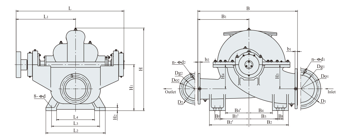
| Type | The dimensions of the pump figure | The dimensions of the input flange | The dimensions of the output flange | ||||||||||||||||||||||||||||
| L | L1 | L2 | L3 | L4 | B | B1 | B2 | B2 ' | B3 | B3 ' | B4 | B4 ' | B5 | B5' | H | H1 | H2 | H3 | H4 | 4-φd | Dg1 | Do1 | D1 | B1 | n-φd1 | DG2 | Do2 | D2 | B2 | n-φd2 | |
| 1200S-24 | 2480 | 1370 | 1450 | 1200 | 950 | 3000 | 1400 | 1000 | 1000 | 700 | 700 | 600 | 600 | 200 | 200 | 2700 | 1700 | 60 | 850 | 975 | 8-F42 | 1200 | 1380 | 1455 | 56 | 32-F40 | 1000 | 1160 | 1230 | 50 | 28-F37 |
| 1200S-39 | 3295 | 1700 | 1680 | 1250 | 900 | 2800 | 1250 | 1100 | 1100 | 875 | 875 | 790 | 790 | 150 | 150 | 2700 | 1650 | 80 | 870 | 1020 | 8-F48 | 1200 | 1380 | 1455 | 56 | 32-F40 | 1000 | 1160 | 1230 | 50 | 28-F37 |
| 1200s-39a | |||||||||||||||||||||||||||||||
| 1200s-39B | |||||||||||||||||||||||||||||||
| 1200S-56 | 3295 | 1700 | 1680 | 1250 | 900 | 2800 | 1250 | 1100 | 1100 | 875 | 875 | 790 | 790 | 150 | 150 | 2700 | 1650 | 80 | 870 | 1020 | 8-F48 | 1200 | 1380 | 1455 | 56 | 32-F40 | 1000 | 1160 | 1230 | 50 | 28-F37 |
| 1200S-56A | |||||||||||||||||||||||||||||||
| 1200S-56B | |||||||||||||||||||||||||||||||
| 1200S-76 | 2840 | 1500 | 1750 | 1500 | 1250 | 2800 | 1250 | 1100 | 900 | 850 | 650 | 750 | 550 | 150 | 150 | 2700 | 1650 | 80 | 870 | 950 | 8-F48 | 1200 | 1380 | 1455 | 56 | 32-F40 | 1000 | 1160 | 1230 | 50 | 28-F37 |
| 1200S-76A | |||||||||||||||||||||||||||||||
| 1200S-76B | |||||||||||||||||||||||||||||||
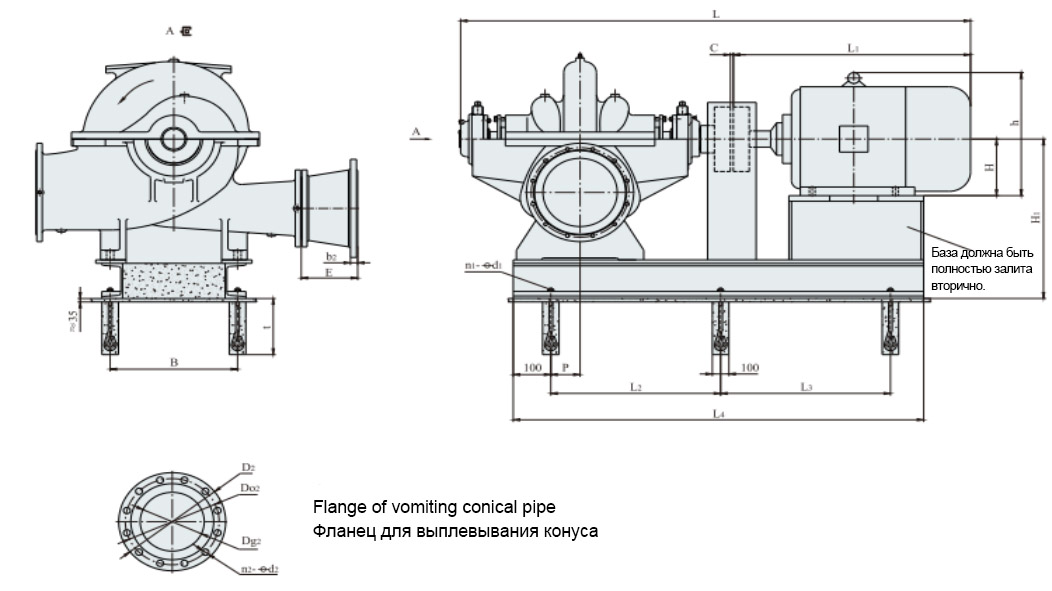
| Type | C | Engine | Engine size | Foundation size |
E | H1 | L | t | Gloric pipe flange | |||||||||||||
| Engine type | Power (KW) |
Voltage (V) |
L1 | h | H | L2 | L3 | L4 | P | B | n1-φd1 | D2 | Do2 | DG2 | B2 | n2-φd2 | ||||||
| 150S-100 | 4 | Y280S-2 | 75 | 380 | 1000 | 640 | 280 | 550 | 550 | 1375 | 75 | 457 | 6-F20 | 300 | 425 | 1723 | 350 | 150 | 280 | 240 | 24 | 8-F23 |
| 150S-78 | 4 | Y250M-2 | 55 | 380 | 930 | 575 | 250 | 520 | 520 | 1294 | 75 | 406 | 6-F20 | 300 | 425 | 1640 | 350 | 150 | 280 | 240 | 24 | 8-F23 |
| 150S-78A | 4 | Y225M-2 | 45 | 380 | 815 | 530 | 225 | 480 | 480 | 1195 | 356 | 1525 | ||||||||||
| 150S-50 | 4 | Y200L2-2 | 37 | 380 | 775 | 475 | 200 | 470 | 470 | 1170 | 100 | 380 | 6-F20 | 300 | 425 | 1484 | 350 | 150 | 280 | 240 | 24 | 8-F23 |
| 150S-50A | 4 | Y200L1-2 | 30 | 380 | 775 | 475 | 200 | 470 | 470 | 1170 | 1484 | |||||||||||
| 150S-50B | 4 | Y180M-2 | 22 | 380 | 670 | 430 | 180 | 450 | 450 | 1095 | 1379 | |||||||||||
| 200S-63 | 4 | Y280S-2 | 75 | 380 | 1000 | 640 | 280 | 570 | 570 | 1372 | 75 | 457 | 6-F20 | 350 | 495 | 1750 | 350 | 200 | 335 | 295 | 26 | 8-F23 |
| 200S-63A | 4 | Y250M-2 | 55 | 380 | 930 | 575 | 250 | 550 | 550 | 1308 | 406 | 1680 | ||||||||||
| 200S-42 | 4 | Y225M-2 | 45 | 380 | 815 | 530 | 225 | 460 | 460 | 1212 | 75 | 400 | 6-F20 | 350 | 495 | 1564 | 350 | 200 | 335 | 295 | 26 | 8-F23 |
| 200S-42A | 4 | Y200L2-2 | 37 | 380 | 775 | 475 | 200 | 480 | 480 | 1184 | 280 | 1524 | ||||||||||
| 250S-39 | 4 | Y280S-4 | 75 | 380 | 1000 | 640 | 280 | 620 | 620 | 1565 | 65 | 450 | 6-F25 | 300 | 610 | 1931 | 450 | 250 | 390 | 350 | 28 | 12-F23 |
| 250s-39a | 4 | Y250M-4 | 55 | 380 | 930 | 575 | 250 | 550 | 550 | 1417 | 560 | 6-F20 | 590 | 1861 | 350 | |||||||
| 250S-24 | 4 | Y225M-4 | 45 | 380 | 845 | 530 | 225 | 520 | 520 | 1400 | 120 | 450 | 6-F20 | 300 | 590 | 1784 | 350 | 250 | 390 | 350 | 28 | 12-F23 |
| 250S-24A | 4 | Y225S-4 | 37 | 380 | 820 | 530 | 225 | 550 | 550 | 1375 | 1759 | |||||||||||
| 250S-14 | 4 | Y200L-4 | 30 | 380 | 775 | 475 | 200 | 520 | 520 | 1306 | 120 | 450 | 6-F20 | 300 | 590 | 1654 | 350 | 250 | 390 | 350 | 28 | 12-F23 |
| 250S-14A | 4 | Y180M-4 | 18.5 | 380 | 670 | 430 | 180 | 520 | 520 | 1234 | 1549 | |||||||||||
| 300S-32 | 4 | Y280M-4 | 90 | 380 | 1050 | 640 | 280 | 740 | 740 | 1710 | 150 | 560 | 6-F20 | 300 | 690 | 2150 | 350 | 300 | 440 | 400 | 28 | 12-F23 |
| 300S-32A | 4 | Y280S-4 | 75 | 380 | 1000 | 640 | 280 | 740 | 740 | 1660 | 2100 | |||||||||||
| 300S-19 | 4 | Y250M-4 | 55 | 380 | 930 | 575 | 250 | 600 | 600 | 1525 | 165 | 550 | 6-F20 | 300 | 670 | 1922 | 350 | 300 | 440 | 400 | 28 | 12-F23 |
| 300S-19A | 4 | Y225M-4 | 45 | 380 | 845 | 530 | 225 | 590 | 590 | 1460 | 1837 | |||||||||||
| 300S-12 | 4 | Y225S-4 | 37 | 380 | 820 | 530 | 225 | 600 | 600 | 1450 | 165 | 550 | 6-F20 | 670 | 1827 | 350 |
|
|||||
| 300S-12A | 4 | Y200L-4 | 30 | 380 | 775 | 475 | 200 | 580 | 580 | 1415 | 1782 | |||||||||||
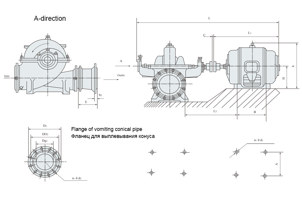
| Type | C | Engine | Engine size | E | L | L2 | Gloric pipe flange | |||||||||||
| Engine type | Power (KW) |
Voltage (V) |
L1 | H | h | B | A | n-φd1 | DG2 | D2 | Do2 | B2 | n-φd2 | |||||
| 150S-100 | 4 | Y280S-2 | 75 | 380 | 1000 | 280 | 640 | 368 | 457 | 4-F24 | 300 | 150 | 280 | 240 | 24 | 8-F23 | ||
| 150S-78 | Y250M-2 | 55 | 380 | 930 | 250 | 575 | 349 | 406 | 4-F24 | 1647.5 | 569 | |||||||
| 150S-78A | Y225M-2 | 45 | 815 | 225 | 530 | 311 | 356 | 4-F19 | 1532.5 | 520 | ||||||||
| 150S-50 | 4 | Y200L2-2 | 37 | 380 | 775 | 200 | 475 | 305 | 318 | 4-F19 | 300 | 1492.5 | 504 | |||||
| 150S-50A | Y200L1-2 | 30 | 775 | 200 | 475 | 305 | 318 | 4-F19 | 1492.5 | 504 | ||||||||
| 150S-50B | Y180M-2 | 22 | 670 | 180 | 430 | 241 | 279 | 4-F15 | 1387.5 | 492 | ||||||||
| 200S-95 | 4 | Y315m-2 | 132 | 380 | 1310 | 315 | 865 | 457 | 508 | 4-F28 | 375 | 2164.5 | 695 | 200 | 335 | 295 | 26 | 8-F23 |
| 200S-95A | Y315S-2 | 110 | 1240 | 315 | 865 | 406 | 508 | 4-F28 | 2094.5 | 695 | ||||||||
| 200S-95B | Y280S-2 | 75 | 1000 | 280 | 640 | 368 | 457 | 4-F24 | 1854.5 | 669 | ||||||||
| 200S-63 | 4 | Y280S-2 | 75 | 380 | 1000 | 280 | 640 | 368 | 457 | 4-F24 | 350 | 1747.5 | 603 | 200 | 335 | 295 | 26 | 8-F23 |
| 200S-63A | Y250M-2 | 55 | 930 | 250 | 575 | 349 | 406 | 4-F24 | 1677.5 | 581 | ||||||||
| 200S-42 | 4 | Y225M-2 | 45 | 380 | 815 | 225 | 530 | 311 | 356 | 4-F19 | 350 | 1562.5 | 532 | 200 | 335 | 295 | 26 | 8-F23 |
| 200S-42A | Y200L2-2 | 37 | 775 | 200 | 475 | 305 | 318 | 4-F19 | 1522.5 | 516 | ||||||||
| 250S-65 | 4 | Y315m-4 | 132 | 380 | 1340 | 315 | 865 | 457 | 508 | 4-F28 | 500 | 2444.5 | 777 | 250 | 390 | 350 | 28 | 12-F23 |
| 250s-65A | Y280M-4 | 90 | 1050 | 280 | 640 | 419 | 457 | 4-F24 | 2154.5 | 721 | ||||||||
| 250S-3g | 4 | Y280S-4 | 75 | 380 | 1000 | 280 | 640 | 368 | 457 | 4-F24 | 300 | 1987.5 | 711 | 250 | 390 | 350 | 28 | 12-F23 |
| 250s-39a | Y250M-4 | 55 | 930 | 250 | 575 | 349 | 406 | 4-F24 | 1917.5 | 689 | ||||||||
| 250S-24 | 4 | Y225M-4 | 45 | 380 | 845 | 225 | 530 | 311 | 356 | 4-F19 | 300 | 1787.5 | 635 | 250 | 390 | 350 | 28 | 12-F23 |
| 250S-24A | Y225S-4 | 37 | 820 | 225 | 530 | 286 | 356 | 4-F19 | 1762.5 | |||||||||
| 250S-14 | 4 | Y200L-4 | 30 | 380 | 775 | 200 | 475 | 305 | 318 | 4-F19 | 1671.5 | 557 | ||||||
| 250S-14A | Y180M-4 | 18.5 | 670 | 180 | 430 | 241 | 279 | 4-F15 | 1566.5 | 545 | ||||||||
| 300S-90 | 5 | Y3554-4 | 315 | 6000 | 1820 | 355 | 780 | 900 | 630 | 4-F28 | 500 | 2998.5 | 949 | 300 | 440 | 400 | 28 | 12-F23 |
| Type | C | Engine | Engine size |
E | L | L2 | Gloric pipe flange | |||||||||||
| Engine type | Power (KW) |
Voltage (V) |
L1 | H | h | B | A | n-φd1 | DG2 | D₂ | Do2 | B2 | n-φd2 | |||||
| 300S-90A | 5 | Y3553-4 | 280 | 6000 | 1820 | 355 | 780 | 900 | 630 | 4-F28 | 500 | 2998.5 | 949 | 300 | 440 | 400 | 28 | 12-F23 |
| 300S-90B | Y3551-4 | 220 | 1820 | 355 | 780 | 900 | 630 | 4-F28 | 2998.5 | |||||||||
| 300S-58 | 4 | Y315l2-4 | 200 | 380 | 1340 | 315 | 865 | 508 | 508 | 4-F28 | 300 | 2483.5 | 795 | 300 | 440 | 400 | 28 | 12-F23 |
| 300S-58A | Y315l1-4 | 160 | 1340 | 315 | 865 | 508 | 508 | 4-F28 | 2483.5 | |||||||||
| 300S-58B | Y315m-4 | 132 | 1340 | 315 | 865 | 457 | 508 | 4-F28 | 2483.5 | |||||||||
| 300S-32 | 4 | Y280M-4 | 90 | 380 | 1050 | 280 | 640 | 419 | 457 | 4-F24 | 300 | 2153.5 | 714 | 300 | 440 | 400 | 28 | 12-F23 |
| 300S-32A | Y280S-4 | 75 | 1000 | 280 | 640 | 368 | 457 | 4-F24 | 2103.5 | |||||||||
| 300S-19 | 4 | Y250M-4 | 55 | 380 | 930 | 250 | 575 | 349 | 406 | 4-F24 | 300 | 1912.5 | 624 | 300 | 440 | 400 | 28 | 12-F23 |
| 300S-19A | Y225M-4 | 45 | 845 | 225 | 530 | 311 | 356 | 4-F19 | 1827.5 | 605 | ||||||||
| 300S-12 | 4 | Y225S-4 | 37 | 380 | 820 | 225 | 530 | 286 | 356 | 4-F19 | _ | 1832.5 | 620 | _ | _ | _ | _ | _ |
| 300S-12A | Y200L-4 | 30 | 775 | 200 | 475 | 305 | 318 | 4-F19 | 1787.5 | 574 | ||||||||
| 350S-125 | 7 | Y4502-4 | 710 | 6000 | 2080 | 450 | 935 | 1120 | 800 | 4-F35 | 750 | 3517.5 | 1123 | 350 | 520 | 470 | 38 | 16-F25 |
| 350S-125A | Y4501-4 | 630 | 2080 | 450 | 935 | 1120 | 800 | 4-F35 | 3517.5 | 1123 | ||||||||
| 350S-125B | Y4004-4 | 500 | 1940 | 400 | 835 | 1000 | 710 | 4-F35 | 3377.5 | 1103 | ||||||||
| 350S-75 | 5 | Y4001-4 | 355 |
6000 6000 6000 |
1940 | 400 | 835 | 1000 | 710 | 4-F35 | 500 | 3191.5 | 980 | 350 | 500 | 460 | 30 | 16-F23 |
| 350s-75a | Y3553-4 | 280 | 1820 | 355 | 780 | 900 | 630 | 4-F28 | 3071.5 | 960 | ||||||||
| 350s-75B | Y3551-4 | 220 | 1820 | 355 | 780 | 900 | 630 | 4-F28 | 3071.5 | 960 | ||||||||
| 350S-44 | 5 | Y3551-4 | 220 | 6000 | 1820 | 355 | 780 | 900 | 630 | 4-F28 | 300 | 3057.5 | 955 | 350 | 500 | 460 | 30 | 16-F23 |
| 350S-44A | Y315l1-4 | 160 | 380 | 1340 | 315 | 865 | 508 | 508 | 4-F28 | 2577.5 | 856 | |||||||
| 350S-26 | 4 | Y315m-4 | 132 | 380 | 1340 | 315 | 865 | 457 | 508 | 4-F28 | 300 | 2514.5 | 726 | 350 | 500 | 460 | 30 | 16-F23 |
| 350s-26A | Y280M-4 | 90 | 380 | 1050 | 280 | 640 | 419 | 457 | 4-F24 | 2224.5 | 706 | |||||||
| Type | C | Engine | Engine size | E | L | L2 | Gloric pipe flange | |||||||||||
| Engine type | Power (KW) |
Voltage (V) |
L1 | H | h | B | A | n-φd1 | DG2 | D2 | Do2 | B2 | n-φd2 | |||||
| 350S-16 | 4 | Y280S-4 | 75 | 380 | 1000 | 280 | 640 | 368 | 457 | 4-F24 | _ | 2132.5 | 684 | _ | _ | _ | _ | _ |
| 350S-16A | Y250s-4 | 55 | 380 | 930 | 250 | 575 | 349 | 406 | 4-F24 | 2062.5 | 1169 | |||||||
| 500S-98 | 7 | Y5002-6 | 800 | 6000 | 2550 | 500 | 1040 | 1250 | 900 | 4-F42 | 1000 | 4196.5 | 1354 | 500 | 670 | 620 | 34 | 20-F25 |
| 500S-98A | Y4504-6 | 630 | 6000 | 2120 | 450 | 935 | 1120 | 800 | 4-F35 | 3766.5 | 1234 | |||||||
| 500S-98B | Y4503-6 | 560 | 6000 | 2120 | 450 | 935 | 1120 | 800 | 4-F35 | 3766.5 | 1234 | |||||||
| 500S-59 | 7 | Y4501-6 | 450 | 6000 | 2120 | 450 | 935 | 1120 | 800 | 4-F35 | 800 | 3766.5 | 1229 | 500 | 670 | 620 | 34 | 20-F25 |
| 500S-59A | Y4005-6 | 400 | 6000 | 1940 | 400 | 835 | 1000 | 710 | 4-F35 | 3586.5 | 1169 | |||||||
| 500S-59B | Y4003-6 | 315 | 6000 | 1940 | 400 | 835 | 1000 | 710 | 4-F35 | 3586.5 | 1169 | |||||||
| 500S-35 | 6 | Y4002-6 | 280 | 6000 | 1940 | 400 | 835 | 1000 | 710 | 4-F35 | 800 | 3309.5 | 1017 | 500 | 670 | 620 | 34 | 20-F25 |
| 500S-35A | Y3553-6 | 220 | 6000 | 1820 | 355 | 780 | 900 | 630 | 4-F28 | 3189.5 | 997 | |||||||
| 500S-22 | 6 | Y3553-6 | 220 | 6000 | 1820 | 355 | 780 | 900 | 630 | 4-F28 | 600 | 3221.5 | 1010 | 500 | 670 | 620 | 34 | 20-F25 |
| 500S-22A | Y315l2-6 | 132 | 380 | 1340 | 315 | 865 | 508 | 508 | 4-F28 | 2741.5 | 871 | |||||||
| 500S-13 | 5 | Y315l1-6 | 110 | 380 | 1340 | 315 | 860 | 508 | 508 | 4-F28 | _ | 2653.5 | 815.5 | _ | _ | _ | _ | _ |
| 600S-75 | 7 | Y5003-6 | 900 | 6000 | 2550 | 500 | 1040 | 1250 | 900 | 4-F42 | 600 | 4251.5 | 1292 | 500 | 670 | 620 | 34 | 20-F25 |
| 600S-75A | Y5002-6 | 800 | 6000 | 2550 | 500 | 1040 | 1250 | 900 | 4-F42 | 4251.5 | 1292 | |||||||
| 600S-47 | 7 | Y4503-6 | 560 | 6000 | 2120 | 450 | 935 | 1120 | 800 | 4-F35 | 600 | 3821.5 | 1172 | 500 | 670 | 620 | 34 | 20-F25 |
| 600S-32 | 6 | Y4005-6 | 400 | 6000 | 1940 | 400 | 835 | 1000 | 710 | 4-F35 | _ | 3573.5 | 1053 | _ | _ | _ | _ | _ |
| 600S-32A | Y4002-6 | 280 | 6000 | 1940 | 400 | 835 | 1000 | 710 | 4-F35 | 3555.5 | 1053 | |||||||
| 600S-32B | 6 | Y3554-6 | 250 | 6000 | 1820 | 355 | 780 | 900 | 630 | 4-F32 | _ | 3435.5 | 1013 | _ | _ | _ | _ | _ |
| 600S-22 | Y3554-6 | 250 | 6000 | 1820 | 355 | 780 | 900 | 630 | 4-F32 | 3292.5 | 956 | |||||||
| 600S-22A | Y3553-6 | 220 | 6000 | 1820 | 355 | 780 | 900 | 630 | 4-F28 | 3292.5 | 956 | |||||||
| Type | C | Engine | Engine size | E | L | L2 | Gloric pipe flange | |||||||||||
| Engine type | Power (KW) |
Voltage (V) |
L1 | H | h | B | A | n-φd1 | DG2 | D2 | Do2 | B2 | n-φd2 | |||||
| 800S-22 | 6 | Y450-8 | 450 | 380 | 2080 | 450 | 1650 | 1120 | 800 | 4-F35 | 800 | 4190 | 1191 | 800 | 1015 | 950 | 42 | 24-F33 |
| Y450-10 | 250 | 2080 | 450 | 1650 | 1120 | 800 | 4-F35 | 4190 | 1191 | |||||||||
| 800S-22A | Y450-8 | 315 | 2080 | 450 | 1650 | 1120 | 800 | 4-F35 | 4190 | 1191 | ||||||||
| Y355l-10 | 185 | 1590 | 355 | 990 | 630 | 610 | 4-F28 | 3700 | 1050 | |||||||||
| Y450-10 | 200 | 2080 | 450 | 1650 | 1120 | 800 | 4-F35 | 4190 | 1191 | |||||||||
| 800S-32 | 7 | Y500-8 | 630 | 6000 | 2220 | 500 | 1900 | 1250 | 900 | 4-F42 | 4530 | 1457 | ||||||
| Y450-10 | 315 | 2080 | 450 | 1650 | 1120 | 800 | 4-F35 | 4390 | 1337 | |||||||||
| 800S-32A | Y450-8 | 450 | 2080 | 450 | 1650 | 1120 | 800 | 4-F35 | 4390 | 1337 | ||||||||
| Y450-10 | 250 | 2080 | 450 | 1650 | 1120 | 800 | 4-F35 | 4390 | 1337 | |||||||||
| 800S-47 | 8 | Y1000-8/1180 | 1000 | 2480 | 930 | 1690 | 1800 | 1400 | 4-F48 | 4990 | 1368 | |||||||
| Y500-10 | 450 | 2220 | 500 | 1900 | 1250 | 900 | 4-F42 | 4730 | 1593 | |||||||||
| 800s-47a | Y500-8 | 710 | 2220 | 500 | 1900 | 1250 | 900 | 4-F42 | 4730 | 1593 | ||||||||
| Y450-10 | 355 | 2080 | 450 | 1650 | 1120 | 800 | 4-F35 | 4590 | 1473 | |||||||||
| 800S-76 | Y1600-8/1430 | 1600 | 2690 | 950 | 1860 | 1900 | 1750 | 4-F48 | 1000 | 4970 | 1423 | |||||||
| Y800-10/1180 | 800 | 2380 | 930 | 1690 | 1700 | 1400 | 4-F48 | 4660 | 1343 | |||||||||
| 800S-76A | Y1250-8/1430 | 1250 | 2540 | 930 | 1860 | 1800 | 1750 | 4-F48 | 4820 | 1373 | ||||||||
| Y500-10 | 630 | 2220 | 500 | 1900 | 1250 | 900 | 4-F42 | 4500 | 1568 | |||||||||
| 800S-76B | Y1000-8/1180 | 1000 | 2480 | 930 | 1690 | 1800 | 1400 | 4-F48 | 4760 | 1343 | ||||||||
| Y500-10 | 500 | 2220 | 500 | 1900 | 1250 | 900 | 4-F42 | 4500 | 1568 | |||||||||
| Type | Engine | Foot valve P=0.25MPa |
Water filter (Code) |
Actuator P = 1MPA |
Check valve P = 1MPA |
Comic vomiting pipe (code) |
Foundation (Code) |
B4201 | |
| Type | Power (KW) |
Hook key | |||||||
| (Code) | |||||||||
| 150S-100 | Y280S-2 | 75 | Φ150 | — | Φ150 | Φ150 | Z100×10-150×10 | 150S100-Y280S-2 | 4552 |
| 150S-78 | Y250M-2 | 55 | Φ150 | — | Φ150 | Φ150 | Z100×10-150×10 | 150S78-Y250M-2 | 4552 |
| 150S-78A | Y225M-2 | 45 | 150S78-Y225M-2 | ||||||
| 150S-50 | Y200L2-2 | 37 | Φ150 | — | Φ150 | Φ150 | Z100×10-150×10 | 150S50-Y200L-2 | 4552 |
| 150S-50A | Y200L1-2 | 30 | |||||||
| 150S-50B | Y180M-2 | 22 | 150S50-Y180M-2 | ||||||
| 200S-95 | Y315m-2 | 132 | Φ200 | — | Φ200 | Φ200 | Z125×10-200×10 | 200S95-y315m-2 | 6872 |
| 200S-95A | Y315S-2 | 110 | 200S95-Y315S-2 | ||||||
| 200S-95B | Y280S-2 | 75 | 200S95-Y280S-2 | ||||||
| 200S-63 | Y280S-2 | 75 | Φ200 | — | Φ200 | Φ200 | Z150×10-200×10 | 200S63-Y280S-2 | 4552 |
| 200S-63A | Y250M-2 | 55 | 200S63-Y250M-2 | ||||||
| 200S-42 | Y225M-2 | 45 | Φ200 | — | Φ200 | Φ200 | Z150×10-200×10 | 200S42-y225m-2 | 4552 |
| 200S-42A | Y200L2-2 | 37 | 200S42-Y200L-2 | ||||||
| 250S-65 | Y315m-4 | 132 | Φ250 | — | Φ 250 | Φ250 | Z150×10-250×10 | 250s65-y315m-4 | 7885 |
| 250s-65A | Y280M-4 | 90 | 250S65-Y280M-4 | ||||||
| 250S-39 | Y280S-4 | 75 | Φ250 | Φ250 | Φ250 | Z200×10-250×10 | 250s39-y280s-4 | 6872 | |
| 250s-39a | Y250M-4 | 55 | Φ250 | — | Φ250 | Φ250 | Z200×10-250×10 | D250S-39a-y250m-4 | 6872 |
| 250S-24 | Y225M-4 | 45 | Φ250 | — | Φ250 | Φ250 | Z200×10-250×10 | 250s24-y225m-4 | 6872 |
| 250S-24A | Y225S-4 | 37 | 250s24-y225s-4 | ||||||
| 250S-14 | Y200L-4 | 30 | Φ250 | — | Φ250 | — | Z200×10-250×10 | 250S14-Y200L-4 | 4552 |
| 250S-14A | Y180M-4 | 18.5 | 250S14-Y180M-4 | ||||||
| 300S-90 | Y355l-4 | 315 | Φ300 | — | Φ300 | Φ300 | Z200×10-300×10 | 300S90-Y355L(M) | 9095 |
| 300S-90A | Y355l-4 | 280 | |||||||
| 300S-90B | Y355m-4 | 220 | |||||||
| 300S-58 | Y315l2-4 | 200 | Φ300 | — | Φ300 | Φ300 | Z250×10-300×10 | 300S58-Y315L-4 | 7885 |
| 300S-58A | Y315l1-4 | 160 | |||||||
| 300S-58B | Y315m-4 | 132 | 300S58-Y315M-4 | ||||||
Note: the barrel cone and the hook wrench are the pump accessories, others can be provided in accordance with the requirements of the order.
| Type | Engine | Foot valve P=0.25MPa |
Water filter (Code) |
Actuator P = 1MPA |
Check valve P = 1MPA |
Comic vomiting pipe (code) |
Foundation (Code) |
B4201 | |
| Type | Power (KW) |
Hook key | |||||||
| (Code) | |||||||||
| 300S-32 | Y280M-4 | 90 | Φ300 | — | Φ300 | Φ300 | Z250×10-300×10 | 300S32-Y280M-4 | 7885 |
| 300S-32A | Y280S-4 | 75 | 300S32-Y280S-4 | ||||||
| 300S-19 | Y250M-4 | 55 | Φ300 | — | Φ300 | Φ300 | Z250×10-300×10 | 300S19-Y250M-4 | 6872 |
| 300S-19A | Y225M-4 | 45 | 300S19-Y225M-4 | ||||||
| 300S-12 | Y225S-4 | 37 | Φ300 | — | Φ300 | — | — | 300S12-Y225S-4 | 6872 |
| 300S-12A | Y200L-4 | 30 | 300S12-Y200L-4 | ||||||
| 350S-125 | Y4502-4 | 710 | — | L350 (73) |
Φ350 | Φ350 | Z200×16-350×16 | — | 100110 |
| 350S-125A | Y4501-4 | 630 | |||||||
| 350S-125B | Y4004-4 | 500 | |||||||
| 350S-75 | Y4001-4 | 365 | — | L350 (73) |
Φ350 | Φ350 | Z250×10-350×10 | — | 9095 |
| 350s-75a | Y355l-4 | 280 | 350S75-Y355(M)L-4 | ||||||
| 350s-75B | Y355m-4 | 220 | |||||||
| 350S-44 | Y355m-4 | 220 | — | L350 (73) |
Φ350 | Φ350 | Z300×10-350×10 | 350S44-Y355M(L)-4 | 9095 |
| 350S-44A | Y315l1-4 | 160 | 350S44-Y315L-4 | ||||||
| 350S-26 | Y315m-4 | 132 | L350 (73) |
Φ350 | Φ350 | Z300×10-350×10 | 350s26-y315m-4 | 7885 | |
| 350s-26A | Y280M-4 | 90 | 350s26-y280m-4 | ||||||
| 350S-16 | Y280S-4 | 75 | — | L350 (73) |
Φ500 | — | — | 350S16-Y280S-4 | 6872 |
| 350S-16A | Y250M-4 | 55 | 350S16-Y250M-4 | ||||||
| 500S-98 | Y5002-6 | 800 | — | L500 (73) |
Φ500 | Φ500 | — | — | 135145 |
| 500S-98A | Y5001-6 | 710 | |||||||
| 500S-98B | Y4503-6 | 560 | |||||||
| 500S-59 | Y4501-6 | 450 | — | L500 (73) |
Φ500 | Φ500 | Z350×10-500×10 | — |
100110 115130 |
| 500S-59A | Y4005-6 | 400 | |||||||
| 500S-59B | Y4003-6 | 315 | |||||||
| 500S-35 | Y4002-6 | 280 | — | L500 (73) |
Φ500 | Φ500 | Z350×10-500×10 | — | 9095 |
| 500S-35A | Y3553-6 | 220 | |||||||
| 500S-22 | Y3553-6 | 220 | — | L500 (73) |
Φ500 | Φ500 | — | — | 7885 |
| 500S-22A | Y315l2-6 | 132 | 500S22-Y315L-6 | ||||||
Note: the barrel cone and the hook wrench are the pump accessories, others can be provided in accordance with the requirements of the order.
| Type | Engine | Foot valve P=0.25MPa |
Water filter (Code) |
Actuator P = 1MPA |
Check valve P = 1MPA |
Comic vomiting pipe (code) |
Foundation (Code) |
B4201 | |
| Type | Power (KW) |
Hook key | |||||||
| (Code) | |||||||||
| 500S-13 | Y355l1-6 | 110 | — | L500 (73) | Φ500 | Φ500 | — | — | 7885 |
| 600S-75 | Y5003-6 | 900 | — | L600 (73) |
Φ500 | Φ500 | Z400×10-500×10 | — | 135145 |
| 600S-75A | Y5002-6 | 800 | |||||||
| 600S-47 | Y4503-6 | 560 | — | L600(73) | Φ500 | Φ500 | Z400×10-500×10 | — | 135145 |
| 600S-32 | Y4005-6 | 400 | — | L600 (73) |
Φ500 | Φ500 | — | — |
100110 115130 |
| 600S-32A | Y4002-6 | 280 | |||||||
| 600S-32B | Y3554-6 | 250 | |||||||
| 600S-22 | Y3554-6 | 250 | — | L600 (73) |
Φ500 | Φ500 | — | — | 9095 |
| 600S-22A | Y3553-6 | 220 | |||||||
| 800S-22 | Y450-8 | 450 | — | L800 | Φ600 | Φ600 | — | — | 9095 |
| Y450-10 | 250 | ||||||||
| 800S-22A | Y450-8 | 315 | |||||||
| Y355l-10 | 185 | ||||||||
| Y450-10 | 200 | ||||||||
| 800S-32 | Y500-8 | 630 | — | L800 | Φ600 | Φ600 | — | — | 100110 |
| Y450-10 | 315 | ||||||||
| 800S-32A | Y450-8 | 450 | |||||||
| Y500-10 | 250 | ||||||||
| 800S-47 | Y1000-8/1180 | 1000 | — | L800 | Φ600 | Φ600 | — | — | 135145 |
| Y500-10 | 450 | ||||||||
| 800s-47a | Y500-8 | 710 | |||||||
| Y450-10 | 355 | ||||||||
| 800S-76 | Y1600-8/1430 | 1600 | — | L800 | Φ800 | Φ800 | — | — | 135145 |
| Y800-10/1180 | 800 | ||||||||
| 800S-76A | Y1250-8/1430 | 1250 | |||||||
| Y500-10 | 630 | ||||||||
| 800S-76B | Y1000-8/1180 | 1000 | |||||||
| Y500-10 | 500 | ||||||||
Note: the barrel cone and the hook wrench are the pump accessories, others can be provided in accordance with the requirements of the order.

 vertical turbine pump")